Chery S11 / Chery QQ. Manual - part 248
 

  Index      Chery     Chery S11 / Chery QQ - service repair manual


Search            


Content   ..  246  247  248  249   ..


Chery S11 / Chery QQ. Manual - part 248


Chery  QQ  Maintenance Manual         465 Engine Mechanical System


Notice: You should make sure that every 
screw and nut is loosened during the 
process of above-mentioned work,for the 
purpose of camshaft and pulley can rotate 
freely. 
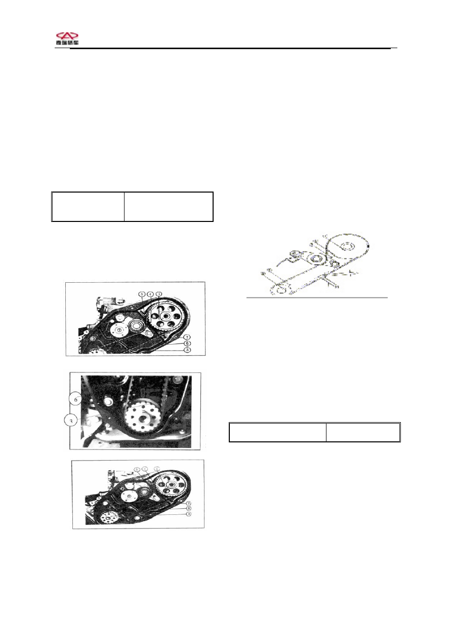
2) There are a dot   on radial line mark   

of camshaft timing belt pulley and another 
dot   on belt rear cover. Run belt pulley to 

align dot   and dot  .

⑤  

3)There is a dot  on

 belt rear cover. Run 

crankshaft to align dot   and dot  .


4) Two timing belt pulleys are aligned with 
each other.Under this circumstances of belt 
being tightened,install the timing belt 
according to the illustration of ⑦ 

- 28 – 


5) After installation of belt,put up one end 
of torsion spring on the tension bracket,put 
up the other end of torsion spring on water 
pump screw,the spring tune-up the belt 
through self own tension,adjust the bolts 
and screws to regulated value. 
Turn crankshaft two circles clockwise and 
adjust the tension wheel bolts and screws 
to the regulated value. 
Notice: Smear GY-340 glue on the screw 
thread of the tension bolts.Fasten the 
adjusting bolts first,then fasten the twisted 
bolt. 

Tensioner bolt 

tighten torque 

14.71~22.56N·m 

(1.5~2.3kg·m) 


Notice: After installation of tension 
pulley,turn crankshaft two circles 
clockwise and check if marks 


①④⑤⑥

aligned with key groove   to a straight 

line after installing tensioner. Repeat 
above-mentioned steps until you are 
satisfied.


6)Press belt between camshaft and 
crankshaft by hand to make sure that 
tension is in the regulated scale. 

  (L)timing belt tension 

5.5~6.5 mm

7) Adjust belt tension to the regulated 
scope,then tune-up clearance of every 
valve to the regulated value.   


Chapter 8    Replacement of Cylinder Head 

 
1 Steps of removal
 

1 Take off fuel pump relay mounted under 


Chery  QQ  Maintenance Manual         465 Engine Mechanical System


the instrument meter plate. 
Notice: Make the engine working for 5 
seconds in order reduce the pressure of 
system,collect and check up the fuel. 
2 Disconnect negation pole cable of battery 
3 Take off air filter and hose. 
4 Remove cover of coolant reservoir tank 
5 Remove low pressure hose of radiator and 
collect the coolant 
6 Remove all hoses and cables which 
connect the cylinder head and intake 
manifold. 
7 Remove high pressure ignition coil 
8 Disconnect the harness of exhaust pipe 
and exhaust manifold 
9 Disconnect oxygen sensor harness 
connector and take off exhaust manifold   
10 Take off timing belt,see the illustration 
for reference. 
11 Take off camshaft timing gear,see the 
illustration for reference. 
12 Remove set bolt from timing belt rear 
cover 
The order is to loosen 1/4 circle,then to 
loosen 1/2 circle,remove the cylinder head 
completely,fasten the bolts

- 28 – 

13 Take off camshaft bracket 

14Remove rocker,rocker seat and rocker 
shaft 
Notice: Don’t confuse in order that you can 
install it to the right position afterwards. 

15 Take off the cylinder head,see the 
contents of relevant chapters for reference. 
 
2 Steps of installation
   
Attention: 
Clean cylinder head completely,remove the 
old gasket,wipe the dirt and residue away. 
Clean cylinder body surface and piston top 
1 Install a new gasket of cylinder  。 
Make sure that the upper mark of gasket is 
upwards and in the front side of the engine. 
2 Fasten cylinder head and cylinder body。 
The fastening bolts order is: from the front 

to the rear,intake side 6237,exhaust side 
5148. 
3 Install camshaft. 
4 Install rocker shaft and racker。 
5 Smear mixture of sealing agent on the 
placing side of crankshaft. 
6 Istall cylinder head set bolt,tighten the 
bolts accordingly. 
7 Install timing belt rear cover set bolt and 
fasten the bolts。 
8 Install camshaft timing gear and 
bolt,fixture。 
9 Install timing belt,see the illustration for 
reference. 
10 Install exhaust manifold and gasket。 
11 Install oxygen sensor to exhaust 
manifold ,make it connected with the wires. 
12 Install exhaust pipe。 
13 Install fuel pipe to fuel oil rail。 
14 Connect high pressure coil harness to 
ignition module connector。 
15 Install hose that connect cylinder head 
and intake manifold,then connect harness。 
16 Connect low pressure hose to radiator。 
17 Fill the coolant in the cooling system,see 
relevant content of article 6.3. 
18 Install air filter and intake hose,then 
connet temperature sensor to harness。 
19 Connect negative pole cable of battery. 


Chery  QQ  Maintenance Manual         465 Engine Mechanical System


Chapter 9      Replacement of Sealing Washer of Valve Spring 

1 Steps of removal 
1 Remove cylinder accordingly. 
2 Remove valve lock from cylindeer head 
assembly. 
3 Take off spring damper. 
4 Take off spring. 
5 Take off sealing washer of valve stem. 
6 Take off valve. 
2 Cleaning 
Clean the combustion chamber.It is 
necessary to put a special brush in the 
drilling machine for check and inspection 
1 Check exhaust pipe and combustion 
chamber whether or not there are some 
cracks 
2 Check to see whether or not there are 
burning trail on the the valve top,check to 
see whether or not there are some cracks in 
the surface and check to see if there are 
some damage of the valve rod. 
3 Check the clearance between the valve rod 
and guide,measure the diameter of valve rod 
in upper,middle and lower position with 
microscope,different value between guide 
and valve rod is the distance of them. 
4 If the distance is not within the scope of   
0.020-0.050 mm,intake and exhaust 0.030 
and 0.060 mm,you should enlarge the hole 
in order that you can install the valve of 
much larger size. 

- 29 – 

Chery 

5 Check the concentricity of maximal ring 
and minimal ring of valve seat. 
standard:0.05 mm 
Width of intake and exhaust valve should be 

1.3-1.5 mm


Chery  QQ  Maintenance Manual         465 Engine Mechanical System


- 28 – 

Chery 


3 Repair of valve seat 

If the valve seat cannot touch the valve 
equably or touch width is not in standard 
scale, the valve and valve seat must be 
repaired by grinding, cutting and polishing. 


1 Exhaust valve seat:Use the taper rymer to 
cut 3 times as shown in figure. First cut at a 
angle of 15°,Then 75°and then 45°to create 
satisfied touch width 
2 Angle of exhaust valve seat 
3 Intake valve seat:cutting sequence is the 
same as the sequence of exhaust valve 
seat,but cutting angle is different,shown as 
the following illustration: 
4 Steps of installation 
1 Install valve. 
2 Install valve stem seal. 
3 Install spring. 
4 Install valve spring damper. 
5 Install valve lock. 
6 Install cylinder head as the following 
illustration. 


Content   ..  246  247  248  249   ..