Chery S11 / Chery QQ. Manual - part 219
SQR7080 Maintenance Manual 372 Engine Mechanical System
19
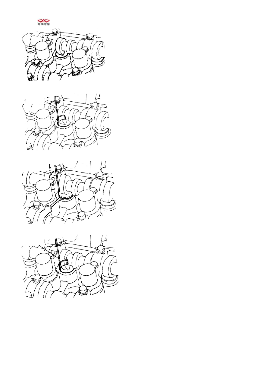
(3) Put SST on the valve thrusting rod from inside of
cylinder head,pay attention noy to press the adjusting
gasket,shown as the illustration.
(4) Turn the crankshaft to make the top of the cam
vertically upwards. Use special tools to press down the
valve thrusting rod and hold it in the place firmly.
(5) Use a screwdriver to stir up the separation cushion,
and use magnet bar to remove the separation cushion
from inside.
(6) Turn the crankshaft to make the cam top facing
downward. Press down the valve and use special tools to
remove it.
(7) Turn the crankshaft for 2—3 circles, then confirm
the throttle spacing. If it fails to be within the benchmark
value limits, check and adjust the throttle spacing in the
operational procedures described in (1)—(9).
SST
SST
SST
4. Cylinder head
4-1 Configuration diagram (Do the following operations in the procedures for the dismounting and
installation of the camshaft)