Chery S11 / Chery QQ. Manual - part 206
 

  Index      Chery     Chery S11 / Chery QQ - service repair manual


Search            


Content   ..  204  205  206  207   ..


Chery S11 / Chery QQ. Manual - part 206


 Chery  QQ  Maintenance Manual                     372 EFI System


Step motor 

怠速步进电机


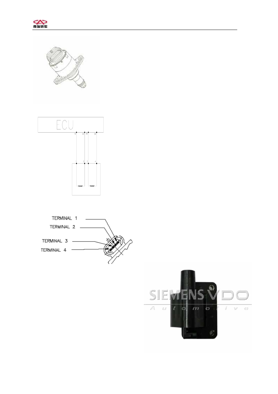
The diagram of step motor 


Pins: 
Pin1: Connect pin 19 on ECU. 
Pin2: Connect pin 20 on ECU. 
Pin3: Connect pin 35 on ECU. 
Pin4: Connect pin 36 on ECU. 
Pin 1 and pin 2 are on one coil and pin 3 and 
pin 4 are on the other. The resistances in 
both coils are same. Please confirm if the 
resistance is in standard values. 


10. Ignition coil ZSK-ROV 
    Function: Ignition coil transforms low 
voltage on primary coil into high voltage on 
secondary coil and produces sparks through 
spark plug to light fuel-air mix in cylinder. 
Independent ignition: There are 3 ignition 
coils on vehicle. ECU will control the 
ground of these coils according to the signal 
of crank position and cam position to control 
ignition of engine. 
Constitute and principle: Ignition coil 
consists of primary coil, secondary coil, iron 
core and shell. When battery voltage 
supplies on primary coil, the coil is charged. 
Once ECU cuts off the return loop of 
primary coil, charging stops. The high 
voltage is induced in secondary coil at same 
time. 
Diagnosis: ECU does not have diagnosis 
function for ignition coil. So if ignition coil 
is fault, DTC does not exist. It can judge if 
the coil works normally only by checking 
resistance of ignition coil. Usually, ignition 
coil produces more heat during the working, 
but over heat of coil will result in increasing 
for coil resistance. It will cause unstable 
running and automatically stopping work for 
engine. 
Primary coil: 0.47 ohms. 
Secondary coil: 8 ohms. 


 Chery  QQ  Maintenance Manual                     372 EFI System


The out view of ignition coil( for 372, there 
3 such coils) 

主继电器


The diagram of ignition coil( with 
distributor) 
Pins: There are 2 pins on low voltage side of 
coil. Pin marked (+) connects battery and the 
other connects ECU. 
 
11. Canister control valve 
Usage: The valve is used to control flux to 
clean canister. The valve is controlled by 
ECU according to engine load, lasting time 
and ferequency of puleses. The fuel vapor in 
canister will accumulate to leak fuel for 
polluting enviroment. The function of   
 
 
canister solenoid is to open the solenoid to 
pass superfluous vapor into intake air pipe to 
be in combustioned. 
Constitue an principle: The valve consists of 
magnetic coil, iron core and vlave body. 
There is filter on inlet. Mass flow through 
the valve is related with the frequency of 
electric pulses that put out to control valve 
by ECU and with the pressure differencial 
between inlet and outlet. If no pulses, 
canister control valve will close. ECU 
controls the electrify time for canister 
solenoid to indirectly control the mass flow 

of clearing air. 
 
Diagnosis: ECU does not have diagnosis 
function for canister control valve, but can 
diagnoses canister control valve driver. 
When canister control valve driver is short 
to battery voltage or over load, short to 
ground and open, the basic self-study of fuel 
metering close-loop control is shut off. If 
canister solenoid is fault, engine will be 
unstable idle or over high idle. 
 

    Out view of canister control valve 


炭罐电磁阀

主继电器


The diagram of canister control valve 
TEV-2 
Pins: There 2 pins on canister control valve. 
One connects pin 87 on main relay and the 
other connects pin 26 on ECU. 


 Chery  QQ  Maintenance Manual                     372 EFI System


12. Steel fuel distribution pipe assembly 
Usage: To store and distribute fuel and 
return superfluous fuel into fuel tank. 
Injector and fuel pressure regulator are 
mounted on the tank to offer stable pressure 
circustance to balance the fuel pressure and 
amount of fuel for smooth running of 
engine. 
 
Constitute: Series 372 fuel distribution pipe 
assembly consists of injector and fuel supply 
pipe aeembly. Since system does not use 
return fuel control, there is no fuel pressure 
regulator. 
 
Install request: Clamp in/out fuel pipe and 
rubber hose with clip. The type of clip 
should be matched with rubber hose to 
insure the seal between in/out fuel pipe and 
the hose. 
 
Diagnosis: Usually, fuel supply pipe   


assembly is seldom to be fault. Mostly bad 
installing causes the fuel leakage. Pay more 
attention during installation. Don’t install 
the seal or o-ring that are used. 


    Fuel distribution pipe assembly 


 Chery  QQ  Maintenance Manual                     372 EFI System


Chapter 2    Basic principle for diagnosis of EFI 

 
(1)  Fault information record 
ECU continually detect the sensors, actuator, related circuit, MIL and battery voltage as well 
as ECU itself, and carry on reliability test for sensor output signal, actuator drive signal and 
internal signal such as oxygen close loop control, knock control, idle control and battery 
voltage control. Once the malfunction in one point is found, or one signal is not true, ECU 
will set the malfunction information record on RAM memory. The record exists as DTC form 
and displays as the order of DTC appearing. Malfunction can de divided as stable malfunction 
or temporary malfunction such as the fault caused by short-lived, harness open or bad contact 
for inserters according to the frequency     
 
(2) Malfunction 

statues 

If the lasting time for one malfunction detected exceeds stable time settled, ECU will consider 
it as a stable fault and stores it as “stable malfunction”. If it disappears, ECU will store it as 
“temporary malfunction” or “not existing”. If it is detected again, it will be “temporary 
malfunction”, but the existing history malfunction does not influence the normal use of 
engine. 
 
(3) Malfunction 

types 

Short to positive pole of battery 
Short to ground 
Open (In the case of up or down resistors, ECU will identify the open fault in input terminal 
as short between input terminal and battery positive pole or short to ground). 


(4)  Limp drive home 
For some important faults detected, if their lasting time exceeds the setting stable time, ECU 
will apply some software methods, for example, to close some control function of oxygen 
sensor close loop control and set substitute value for some unbelievable value. At the moment, 
through the working condition of engine is not so good, but the vehicle can be drive home. In 
this way, vehicle can drive home or service station for repairing to void stop on road. Once 
the fault detected disappears and Hz deducted to 40, the normal values will be used again. 


(5) Warning 

Some 372 of MS200    system vehicles equip MIL. When some important parts such as 

ECU, MAP, TPS, ECT, KS, O2, phase sensor, injector, idle actuator, 2 drive poles of step 
motor, canister control valve, fan repay are fault, ECU will turn MIL on and warning until the 
faults disappear. 


Content   ..  204  205  206  207   ..