Chery S11 / Chery QQ. Manual - part 204
Chery QQ Maintenance Manual 372 EFI System
1
Chapter 1 The princple for EFI and actuator
1.Intake air pressure and intake
Temperature sensor
Usage: Measure baro pressure in manifold and
intake air temperature to supply laod information
for engine.
Constitute and pricinple:The sesor
Consisits of two sensors, MAP and IAT, which
mounted on voltage stablizer box.
MAP: Map consisits of one silicon chip that etched
a film on the chip. There are 4 piezoelectirc
resistances that consist of a Wiston bridge. The
information processing circuit is also on the chip.
The chip consists of closed reference space with a
metal shell. The air absolute pressure in the space
is nearly to zero.
In this way, a micro electric-mechnic system is
formed. The active face of the chip is endured a
pressure nearly to zero, and MAP pressure applies
on the back of the chip through a connecting pipe.
The thickness of the chip is only several microns
(
um),so the change of MAP pressure will
result the mechanical disform for the chip together
with 4 resistances to change their resistance.
The voltage signal that is linearity with pressure is
formed after processing by information processing
circuit in the chip.
Intake air pressure: IAT is a resistor with NTC.
Like coolant temperature sensor, the resistance
decreased with the temperature increasing. ECU in
engine monitors the change of intake air
temperature (conresponding in series circuit).
Diagnosis: The open, short or wear of sensor could
be ditected by the rear electronic unit of MAP.
ECU will judge the malfunction of sensor if the
out put signal exceeds the signal outside the curve
of output feasure.
For examle, if the intake air pressure is higher
than the up limit or lower than lower limit,ECU
will judge thar sensor is malfunction ( The intake
air pressure is below lower limit in starting, but
ECU can juge sarting condition), “CHECK
ENGINE”light will on at same time and engine
will run at malfunction mode. ( The light will not
on for all malfunctions).
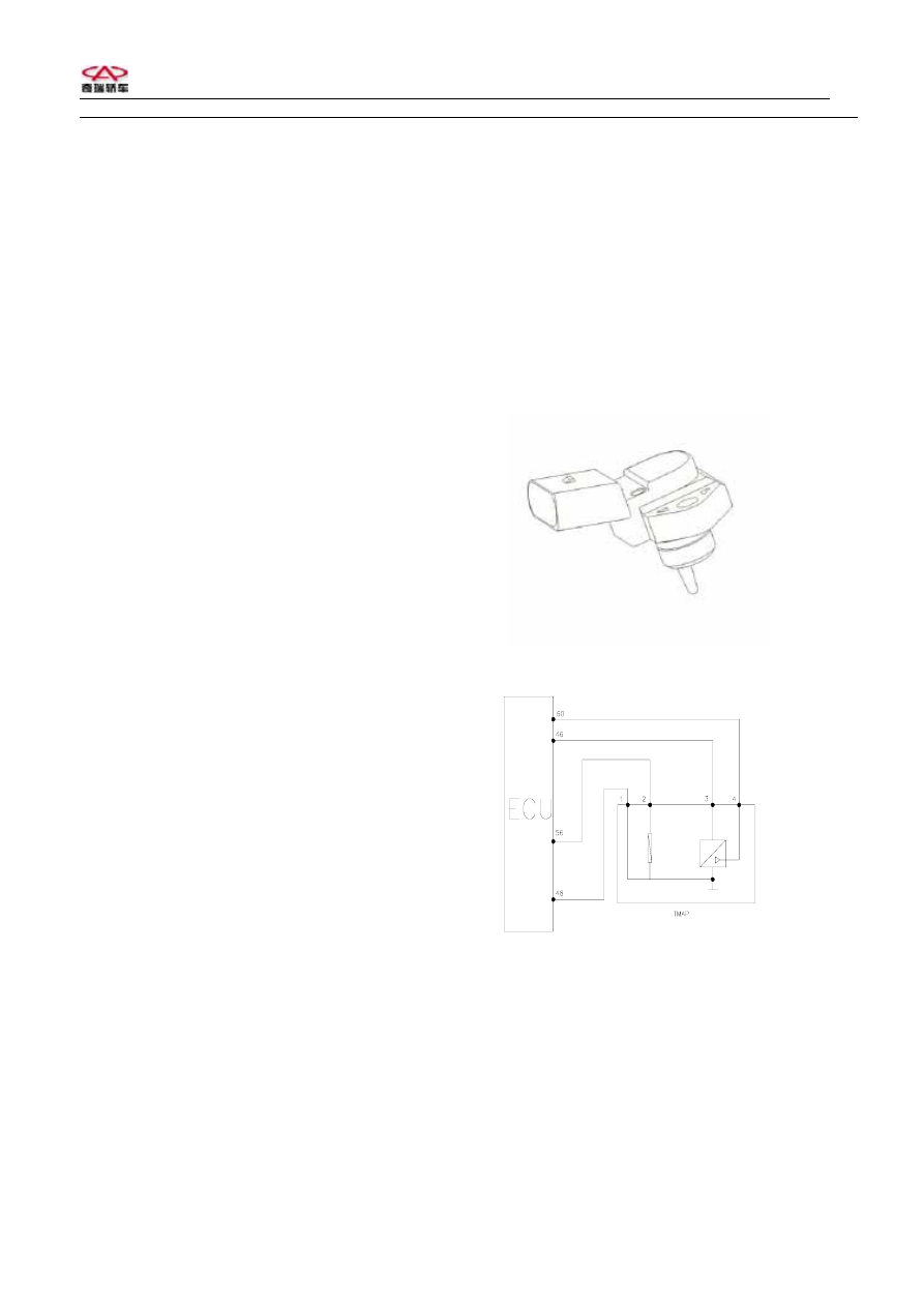
MAP/ IAT
进气压力温度传感器
The circuit for MAR/IAT
MAR/IAT
Pins: No.1 Ground
No.2 Output signal of temperature
No.3 To 5V
No.4 Output pressure signal