Chery S11 / Chery QQ. Manual - part 155
 

  Index      Chery     Chery S11 / Chery QQ - service repair manual


Search            


Content   ..  153  154  155  156   ..


Chery S11 / Chery QQ. Manual - part 155


CHERY SQR7080 EZ Drive SERVICE MANUAL


MECHANICAL TRANSMISSION – WIRE HARNESS 

The  wire  harness  is  integrated  with  the  hydraulic  unit  and  bundles  eleven  connectors  for  different 

components. 

Five main electromagnetic valves are placed together on one sleeve and the plate is fixed onto the hydraulic 

block. 

The electric pump is mounted onto the clutch cylinder body. 

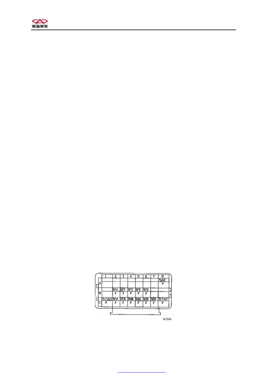
Connection  with  the  vehicle  wire  harness  is  implemented  through  the  24-line  SICMA  connector  on  the 

system. 

Line distribution of the connector: 

A8 - à control + electric pump set 

B2 à control + clutch electromagnetic valve 

B3 à control + gear engagement electromagnetic valve 2 

B4 à control + gear position selection electromagnetic valve 3 

B5 à control + gear engagement electromagnetic valve 1 

B6 à control + gear position selection electromagnetic valve 4 

Sensor: 
– For power on 

C1 --- – For clutch 

– For pressure 

C2 ß gear engagement sensor signal 

C3 ß gear position selection sensor signal 

C4 ß clutch sensor signal 

C5 ß pressure sensor signal 

C6 --- blocky – transmission input speed sensor 

C7 ß signal + transmission input speed sensor 

Control + sensor: 

- For power on 

C8 - à gear position selection 

– For clutch 
– For pressure 

ß - Input 

- à Output 


PDF created with pdfFactory Pro trial version 

www.pdffactory.com


CHERY SQR7080 EZ Drive SERVICE MANUAL


MECHANICAL TRANSMISSION – GEARSHIFT LEVER 

Method of application: 

For  control  lever  type  gearshift,  there  is  only  one 

stable position. 

Any  operation  of  the  gearshift  lever  from  this 

position  will  produce  a  pulse,  which  is  also  called 
“signal”. 


–  Forwards (+): to high drive ratio 
–  Backwards (-): to low drive ratio 
–  Rightwards (N): to the neutral position 
–  Rightwards  and  backwards

:  to  the 

reverse gear 

The  button  “A”  is  used  to  activate  or  inactivate  the 

automatic  mode  depending  on  what  the  driver 

needs. 

The  display  in  the  center  of  the  instrument  board 

indicates the actual drive ratio in  use. The letter 


on  the  base  frame  of  the  gearshift  lever  is  used  to 

indicate that changing to this position will change to 

the reverse gear. 


Operation: 

Its 

control 

of 

the 

automated 

mechanical 

transmission is an electric control. 

Gearshift  lever  position  is  converted  into  electric 

signal  through  the  connector  located  at  the  bottom 

of  the  control  module  and  then  sent  to  the 

transmission computer. 


PDF created with pdfFactory Pro trial version 

www.pdffactory.com


CHERY SQR7080 EZ Drive SERVICE MANUAL


Removal:   

Disconnect the battery. 

Remove: 

–  Gearshift lever base frame dust boot 

–  Transmission base 

Disconnect electric connection of the gearshift lever. 

Take  out  the  following  two  electric  wires  of  the 

gearshift lever's electric connector:   

Line  8  –  power  wire  for  the  automatic  operation 

button 

Line 9 – power wire for the serial operation button 


On the main shaft of the connector, line distribution 

(10 lines) is as follows: 

Line 1: control lever mechanism 

Line 2: information of changing to high drive ratio 

Line 3: information of changing to low drive ratio 

Line 4: stable position information (spare) 

Line  5:  information  of  changing  to  the  neutral 

position 

Line 6: whole module 

Line 7: information of changing to the reverse gear 

Line 8: whole module 

Line  9:  information  of  changing  to  the  automatic 

mode 

Line 10: no connection 


Undo  the  circlip  that  surrounds  the  gearshift  lever 

base washer. 

Remove  the  ball  ring  on  the  top  of  the  gearshift 

lever by applying an upward force on it, as shown in 

the arrow. 


Remove the four fixing bolts for gearshift lever base 

from its mounting base. 

Replace any worn parts. 


Reassembly: 

It  is  easy  to  carry  out  the  reassembly  procedure, 

which is opposite to the disassembly procedure. 


PDF created with pdfFactory Pro trial version 

www.pdffactory.com


CHERY SQR7080 EZ Drive SERVICE MANUAL


MECHANICAL TRANSMISSION – SPECIAL REQUIREMENTS ON REPLACEMENT OF 

SYSTEM AND COMPONENTS 

KIT hydraulic unit/computer/transmission/reprogramming 

(A)  Ignition 

Re-initialization after all experiments (attempts) are carried out: RZ002 attempt” 

(B)  Title: control of VP008 Gear position selection & gear engagement attempt” 

Wait until the program comes to an end 

Turn off the engine 

Wait for one minute 

Ignite the engine (if any fault occurs, the buzzer will be started) 

If  the  check  result  is  OK,  ET061  "Region  Qualified"  will  be  shown.  If  the  “Region  finished”  or 

ET063 Electromagnetic valve is null” is shown, repeat the procedure (B). 

(C)  Apply all drive ratios (the information shown on the display on the instrument board should be OK

(D)  Place the gearshift lever to the neutral position 

Start the engine 

Wait for ten seconds (used in important clutch experiments) and provide no speed. 

If  the  check  result  is  OK,  ET062  “Important  experiments  finished”  will  be  shown.  Otherwise, 

repeat the procedure (D). 

(E)  When  the  "clutch  temperature"  information  PR095  is  less  than  1800C,  repeat  the  engine  start-up 

process with halfload five to six times (used in step-by-step attempt for clutch) 

Turn off the engine 

Wait for one minute 

Ignite the engine 

If  the  check  result  is  OK,  ET065 “Step-by-step  attempt  finished”  will  be  shown.  Check  whether 

the “Step-by-step” information is changing, and if not so, repeat the procedure (E). 

(F) 

Title: control of CF321 “Transmission model” selection: short-size or long-size 

Check  that  the  “Transmission  model”  information  shown  is  really  that  model  that  the  operator 

selected. 

(G)  Turn off the engine 

Engagement position sensor/gear position selection sensor 

(A)  Ignition 

Ensure no fault 

(B)  Title: Control of VP008 "Gear position selection & gear engagement attempt" 

Wait until the program comes to an end 

Wait for one minute 

Ignition (if any fault occurs, the buzzer will be started) 

If  the  check  result  is  OK,  ET061  “Region  Qualified”  will  be  shown.  If  the  “Region  finished”  or 

ET063 “Electromagnetic valve is null” is shown, repeat the procedure (B). 

Apply all drive ratios (the information shown on the display on the instrument board should be OK) 

(C)  Turn off the engine 

Clutch position sensor/clutch 

(A)  Ignition 

Ensure no fault 

PDF created with pdfFactory Pro trial version 

www.pdffactory.com


Content   ..  153  154  155  156   ..