Chery S11 / Chery QQ. Manual - part 47
 

  Index      Chery     Chery S11 / Chery QQ - service repair manual


Search            


Content   ..  45  46  47  48   ..


Chery S11 / Chery QQ. Manual - part 47


Chery QQ Service Manual 

- 4 - 

5.Brush joint not well or wear and tear     

6.Brush spring die down 

7.Rectifier damage 

8.Excitation coil connect earth not well 

9.Armature layer short circuit 

10. The running of crankshaft is not flexible 

Repair or replace 

Replace 

Replace 

Repair  

Replace 

Repair 

Starter motor 

run but slowly 

(Torque is small) 

If battery connection normally, please check 

starter motor 

1.Magnet switch main contact point contact not 

well 

2.Armature layer short circuit 

3.Rectifier burnout or wear and tear   

4.Excitation coil connect earth not well 

5.Brush wear and tear 

6.Brush spring die down 

7.Rectifier end cover damage or wear abnormally 


Replace 


Replace 

Repair or replace 

Repair 

Replace 

Replace spring   

Replace 

Starter motor 

can run but can 

not start the 

crankshaft  

1.Start pinion tooth tip wear and tear   

2.Overspeed clutch slippage is not flexible 

3.Overspeed clutch skid   

4. Gear ring wear and tear   

Replace 

Replace 

Replace 


Section 3 disassemble and r

Suggest: All the parts should be cleaned comp

starter motor bracket, armature, overspeed

should be cleaned by degrease fluid, and blown by compressed air, finally use cloth to 

rub-up.    

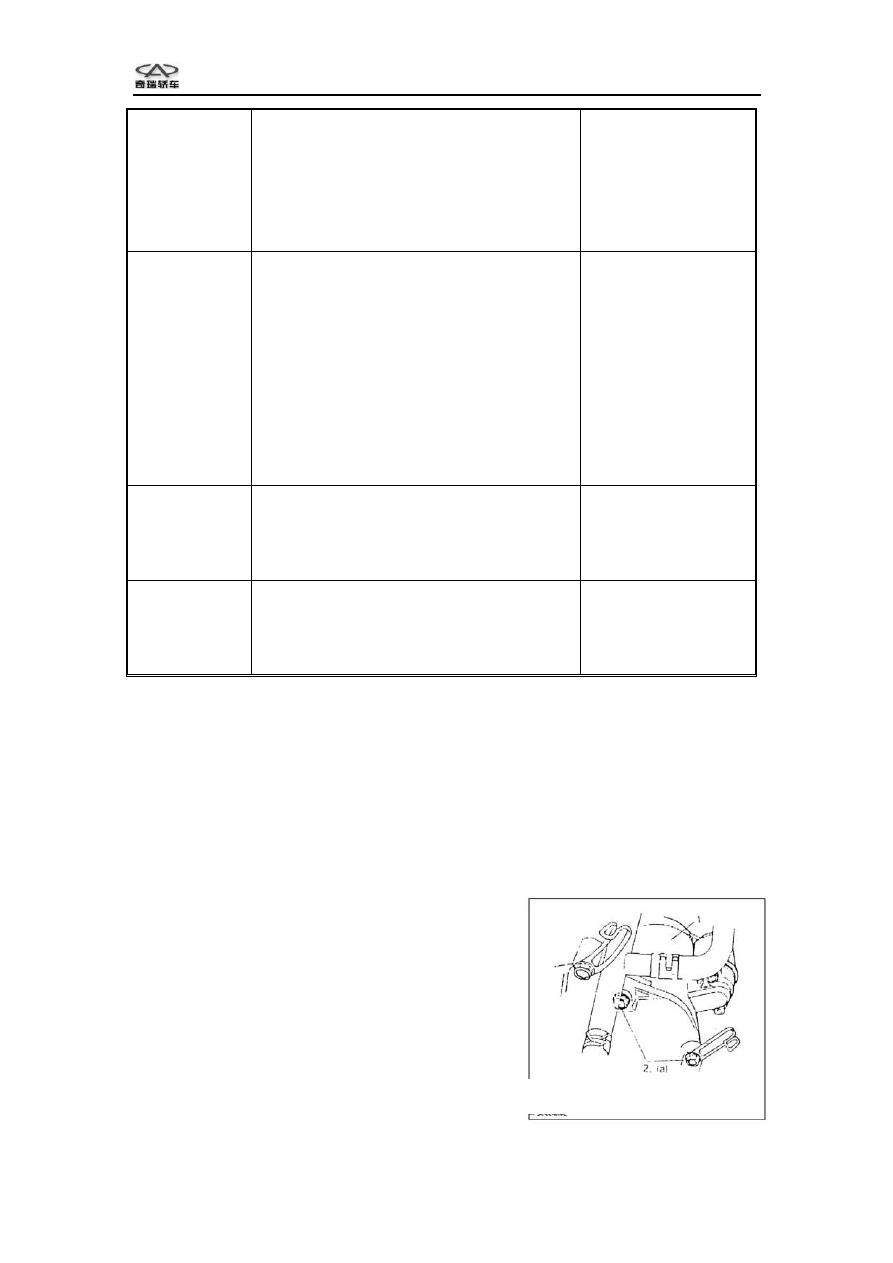
Removal and installation   

1. Disconnect the negative wire of the battery.   

2. Disconnect the magnet switch and its wire   

from the connection post of starter motor. 

3. Remove two fixing bolts.   

4. Remove starter motor.   

5. Installation is in reverse order of removal.   

1.start motor 
2.installation bolt

epair starter motor 


letely when check the starter motor, but 

 clutch, magnet switch and rubber parts 

Replace 

Starter motor 

can not stop 

running  

1.Magnet switch contact point me

2.Magnet switch coil layer short circuit 

3.Ignition switch can not return

position 

lt and integrate  


 to original 

Replace 

Replace 

Replace 


Chery QQ Service Manual 

- 5 - 

Tighten torque   

(a):18~28N.m(1.8--2.8kg—m.13.5—20.01b—ft) 

Magnet switch assembly   

Disassembly 

1. Loose the nut from the magnet switch then 

disconnect wire. 

2. Take two nuts away, draw up the rear part of 

the magnet switch in order to separate the inner 

side hook and fork, then remove magnet switch. 

Caution: Don’t disassemble magnet switch, if 

necessary, please replace the whole assembly.   


Installation  

1. If necessary, magnet switch or protective cover should be replaced by new parts, 

then daub lubricating grease on plunger.   

2. Hook the plunger onto fork, then use nut to fix magnet switch. 

3. Connect the wire, then check the working state of switch. 

Notice:  


Please check the plunger and fork is hooked firmly before install nut. 


Protective cover ventilation side is downward. 


Starter motor assembly   

Disassembly  

1. Remove magnet switch.         

2. Remove two screws, take away the 

rectifier rear cover, armature retainer plate 

and braking spring.   

3. Remove break through bolt, then draw 

out the rectifier end cover.   


1.screw 
2.rectifier end cover
3.armature mainboard

4.brake spring 
5.through bolt 
6.end cover   
7. redirector end cover 

1.magnet switch 

2.protective cover 

3.plunger hook 


Chery QQ Service Manual 

- 6 - 


4. Use long-nose pliers to pull out 

the brush, then remove brush holder


5. Remove starter bracket 

6. Use spring snap ring pliers and screwdriver to remove armature snap ring, then pull 

the pinion


1.start motor
bracket 
2.brush 
3.brush bracket 

 stop ring and overspeed clutch out. 

1.armature 

2.snap ring 

3.drive end cover

1.armature 

2.snap ring   

3.pinion stop ring 

4.overspeed clutch

.   


Chery QQ Service Manual 

- 7 - 


Assembly  

1. Check each part according to the 

method described in section “inspect 

and repair”, if necessary, please 

replace or repair it.   

2. Daub lubricating grease according 

to the figure before install the

overspeed clutch, then use spring snap 

ring to lock the stop ring.   


3. Daub lubricating grease on the fork, 

and make a combination with armature, 

then assemble with drive cover.   


4. Assemble starter motor bracket and 

brush holder, then install four brushes 

and spring.   

Notice:  

Please check armature and rectifier 

disengaged completely or not when 

install the brush holder. 

Check whether brush has unnecessary contact with other parts. 


1.brush bracket   
A: excitation coil wire fix 
B: locate flange by through bolt

cover

1.armature
2.fork 
3.drive 


1.armature  
2.overspeed clutch
3.pinion stop ring 
4.spring snap ring


Content   ..  45  46  47  48   ..