Chery QQ6 (S21) / S12LHD. Manual - part 32
 

  Index      Chery     Chery QQ6 (S21) / S12LHD - service repair manual


Search            


Content   ..  30  31  32  33   ..


Chery QQ6 (S21) / S12LHD. Manual - part 32


125 

Section 3    Electronic Injector Harness 

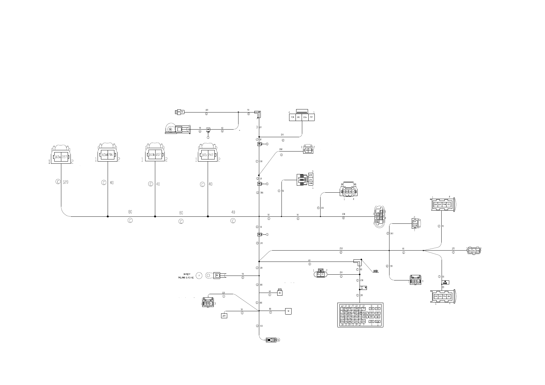
I. Schematic Diagram of Harness 


空气压力传感器

凸轮轴传感器

点火线圈

电子节气门

车速传感器

发电机

倒车灯开关


Injector Nozzle 1 

Injector Nozzle 2 

Injector Nozzle 3 

Injector Nozzle 4 

Generator 

Charging Indicator 

Air Pressure Sensor 

Camshaft Sensor 

Ignition Switch 

Carbon Canister Solenoid Valve 

Rear Oxygen Sensor 

Vehicle Speed Sensor 

Front Oxygen Sensor 

Engine Speed Sensor 

Water  Temperature 
Sensor 

Electronic Throttle 

To ECU Harness 

Power Steering Pump Switch 

Oil Pressure Switch 

Starter 
Controller 

Backup Lamp Switch 

Compressor 

Knock Sensor 

126 

II. Main Connectors Description 


No 

Connector Description 

Number 

of Pin 

Connection 

Remark 

Charging indicator connector 

Charging indicator 


Generator connector 

Generator 


Injector nozzle 1 connector 

Injector nozzle 1 


Injector nozzle 2 connector 

Injector nozzle 2 


Injector nozzle 3 connector 

Injector nozzle 3 


Injector nozzle 4 connector 

Injector nozzle 4 


Air pressure sensor connector 

Air pressure sensor 


Carbon 

canister 

solenoid 

valve 

connector 

Carbon  Canister  Solenoid 

Valve 


Camshaft sensor connector 

Camshaft sensor 


10 

Ignition coil connector 

Ignition Coil 


11 

Electronic throttle    sensor connector 

Electronic throttle sensor 


12 

Engine battery connector 

Starter 


13 

Knock sensor connector 

Knock Sensor 


14 

A/C compressor connector 

A/C compressor 


15 

Starter controller connector 

Starter controller 


16 

Oil pressure switch connector 

Oil pressure switch 


17 

Power steering pump connector 

Power steering pump 


18 

Backup lamp switch connector 

Backup Lamp Switch 


19 

ECU connector 

42 

Engine 

compartment 

harness connector 


20 

Water temperature sensor connector 

Water temperature sensor 


21 

Engine speed sensorconnector 

Engine speed sensor 


22 

Rear oxygen sensorconnector 

Rear oxygen sensor 


23 

Vehicle speed sensor connector 

Vehicle speed sensor 


24 

Front oxygen sensor connector 

Front oxygen sensor 


127 


III. 

Disassembly/Reassembly 

of 

Engine 

Harness 

Part Number: S21-3724180 

(I). Preparation 

Tools: 

socket wrench, cross screwdriver, flat head screwdriver 

(II). Precautions 

Power  OFF  before  the  electrical  elements  and 

harnesses are removed. 

The ignition switch must be in OFF state.   

(III). Removal Procedure 

1.  Disassembly/Reassembly  of  Battery  and  Air 

Cleaner.   

1.1.1. Remove the positive of battery.   


1.1.2. Remove the negative of battery, and take off the 

battery assy.   


1.1.3.  Loosen  the  fixing  nuts  of  air  cleaner  with  a 

sleeve.   


1.1.4. Loosen the fixing nuts of air cleaner inlet with a 

sleeve.   


128 


1.1.5. Pull out the  hose  used to connect the air cleaner 

with engine intake manifold by hand.   


1.1.6. Take off the air cleaner .   


1.1.7. Remove the fixed seat from the battery.   


1.2. Installation 

Install it in the reverse order of removal.   


2.  Disconnect  the  connection  of  all  engine  harness 

connectors.   

2.1.1.  Remove  the  connectors  from  the  electronic 

injector harness and engine compartment harness.   


2.1.2.  Remove  the  connector  from  the  electronic 

throttle.   


Content   ..  30  31  32  33   ..