Chery QQ6 (S21) / S12LHD. Manual - part 17


  Index      Chery     Chery QQ6 (S21) / S12LHD - service repair manual


Search            


Content   ..  15  16  17  18   ..


Chery QQ6 (S21) / S12LHD. Manual - part 17


65 


II.    Removal  of  Instrument 

Panel 

1. 

Disassembly/Reassembly 

of 

Instrument Panel 

1.1. Removal Step 

1.1.1.  Remove  the  steering  wheel  and 

combination  switch  (see  Remova  of  Steering 

Wheel).   

1.1.2  Remove  glove  box  (Refer  to  Removal  of 

glove box) 


1.1.3.  Remove  the  console  panel,  audio  unit, 

emergency switch,  A/C  control switch, ashtray, 

console  (refer  to  Disassembly/Reassembly  and 

Removal  of  Console  Panel,  Audio  Unit, 

Emergency  Switch,  A/C  Control  Switch, 

Ashtray).   

1.1.4  Disassemble  combined  instrument  (Refer 

to Disassembly of Combined Instrument ) 


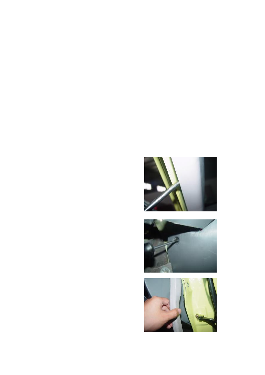
1.1.5.  Remove  the  right/left  A  pillar  upper  and 

lower trims.   


1.1.6.  Remove  the  weatherproof  rubber  strips 

from  the  left  front  and  right  front  door 

openings.   


66 


1.1.7.  Remove  the  left  and  right  air  outlet 

covers  and  exterior  rear-view  mirror  regulating 

switch with a flat head screwdriver.   


1.1.10.  Take  off  the  ornament  cover,  and 

remove  two  fix screws  from  the right and  left 

front parts of upper instrument panel body and 

seven  fix  screws  from  the  lower  instrument 

panel body  with a cross screwdriver, and  then 

take  off  the  upper  instrument  panel  assy 

together with the right and left air outlets. 

Torque: 3±0.5 Nm 


1.1.11.  Remove  the  right  and  left  four  cross 

beams from the instrument panel and the fixing 

bolts from the both sides of vehicle body with a 

10# sleeve.   

Torque: 23±2 Nm 


67 


1.1.12.  Remove  two  cross  beams  from  the 

instrument  panel  and  the  fixing  bolts  from  the 

soleplate with a 10# sleeve.   

Torque: 10±1 Nm 


1.1.13.  Obliquely  place  the  instrument  panel 

and  instrument  panel  cross  beam,  remove  the 

fixing bolts from the left, middle and right sides 

of instrument panel with a 10# sleeve, and take 

off the bond strap.   

Torque: 4±0.5 Nm 


1.1.12. Detach any related harness connector.   


1.1.13.  Lift  out  the  instrument  panel  and 

instrument panel cross beam by two operators.   


1.2. Installation Step 

The  installing  steps  are  reverse  to  those  for 

removal. 

Note: 

1.2.1.  The  instrument  panel  dual-vent  and  A/C 

vent  shall  be  fit  well,  without  the  improper 

installation  and  air  leakage.  The  instrument 

panel air duct and instrument panel cross beam, 

evaporator  and  other  parts  shall  NOT  interfere 

and  affect  the  installation  of  instrument  panel, 

which  may  result  the  improper  installation  of 

instrument panel and its accessories. 

1.2.2.    The  instrument  panel  and  front 

windscreen  shall  NOT  interfere  and  affect  the 

installation  of  instrument  panel  and  front 

windscreen,  and  the  clearance  between  front 

windscreens shall be uniform. 

1.2.3.  The  clearance  between  the  instrument 

panel  and  both  sides  of  body  shall  be  uniform 

and  can  meet  the  assembly  of  weatherproof 

rubber strip of door opening. 


68 


1.2.4.  The  glove  case  switch  shall  be  flexible, 

without  the  interference,  clamped  or  locking 

untightened symptom. 


2. Removal of Instrument Panel    cross 
beam 

2.1. Removal Step 

2.1.1.  Disassemble  instrument  panel  assembly 

(Refer to Disassembly of Instrument Panel) 


2.1.2.  Remove  seven  fix  screws  from  the  air 

duct  as  shown  in  the  figure,  and  then  take  off 

the air duct.   


Content   ..  15  16  17  18   ..