Chery Fora (Elara A520). Manual - part 172


  Index      Chery     Chery Fora (Elara A520) - service repair manual


Search            


Content   ..  170  171  172  173   ..


Chery Fora (Elara A520). Manual - part 172


CHERY A520 SERVICE MANUAL                                QR519 TRANSMISSION 

16 


25.  Screw  out  the  reverse  shift  fork 

mechanism  assembly  bolts  and  remove 
the reverse shift fork; 


Figure 25


26.  Remove  the  split  baffle  ring  with  a 

caliper; 


Figure 26


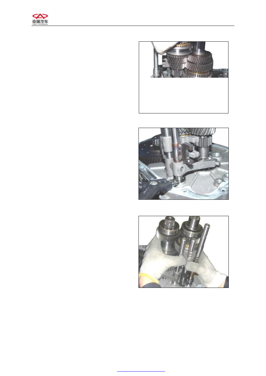
27.  Take  hold  of  the  input  shaft  assembly, 

output shaft assembly, 1st-2nd shift fork, 
3rd-4th  shift  fork  and  5th-reverse  fork 
shaft together  with  your  hands  and  take 
them 

out; 

finally, 

take 

out 

the 

differential assembly; 


Figure 27


CHERY A520 SERVICE MANUAL                                QR519 TRANSMISSION 

17 

VII EXPLODED VIEW 

INPUT SHAFT ASSEMBLY 


  1                2        3        4        5            6        7        8        9            10      11      12      13      14 


                                                                            15          10              8        7        16            17   

Figure 28 

1. Input shaft assembly 
2. Front input shaft bearing 
3. Input shaft 
4. 3rd-5th needle roller bearing 
5. 3rd driving gear assembly 
6. 3rd driving gear 
7. 3rd-4th synchronizer cone 
8. 

Synchronizer 

ring- 

3rd-4th 

synchronizer   
9. 3rd-4th synchronizer assembly 

10. Steel wire spring for 3rd-4th synchronizer 
11. Guide block for 3rd-4th synchronizer 
12. Gear sleeve for 3rd-4th synchronizer 
13. 4th gear needle roller bearing 
14. 4th driving gear assembly 
15. Gear hub for 3rd-4th synchronizer 
16. 4th driving gear 
17. 4th-collar 

CHERY A520 SERVICE MANUAL                                QR519 TRANSMISSION 

18 


DISASSEMBLY: 

If a special tool  is available,  you can directly 
use  it  to  disassemble  the  input  shaft 
assembly.  Otherwise,  use  the  detacher  to 
carefully  pull  out  the  4th-collar,  4th  driving 
gear,  4th  gear  needle  roller  bearing,  3rd-4th 
synchronizer  assembly  and  3rd  driving  gear 
in sequence. 

In  addition,  pull  out  the  front  input  shaft 
bearing from the front end of input shaft.


NOTICE FOR INSTALLATION: 

(1)  Clean all components. 

(2)  Check the input shaft: 

①  Check  whether  there  is  any  damage, 

abnormal  wear  or  lockup  of  the  needle 
roller bearing's outer-diameter portion to 
be mounted. 

②  Check  whether  there  is  any  damage  or 

wear of the spline. 

Check the needle roller bearing – whether the 
input shaft and gears are correctly assembled, 
whether  the  gears  can  rotate  smoothly,  and 
whether there is any part looseness or noise. 

Check the 3rd and 4th driving gears: 

①  Check  whether  there  is  any  damage  or 

wear on tooth surfaces of helical gear (A 
in  Figure  29)  and  clutch  gear  (B  in 
Figure 29).   

②  Check  whether  there  is  any  damage, 

wear or coarsening on the synchronizer's 
conical surface.   

③  Check  whether  there  is  any  damage  or 

wear  on  their  inner-diameter,  front  and 
rear surfaces.


Figure 29


CHERY A520 SERVICE MANUAL                                QR519 TRANSMISSION 

19 


Check  the  gear  sleeve  and  gear  hub  of  the 
3rd-4th synchronizer: 

①  Assemble  the  gear  sleeve  and  gear  hub 

together  and  check  whether  they  can 
slide  smoothly  or  whether  they  are 
locked up (as shown in Figure 30). 

②  Check  whether  there  is  any  damage  in 

the  front  and  rear  of  the  gear  sleeve's 
inner surface. 

Note:  if  it  is  necessary  to  replace  the  gear 
sleeve  or  hub,  you  shall  use  a  new  complete 
set of these components for substitution.


Figure 30


(3)  Clean  the  inner  conical  surfaces  of 

synchronizer  rings  by  steel  wire  brush 
(as shown in Figure 31). 

Check  whether  there  is  any  damage  or  wear 
on the gear tooth surfaces of the synchronizer 
ring, whether there is any damage or wear on 
the 

inner-diameter 

surface 

of 

the 

synchronizer's  conical  portion,  and  whether 
the screw thread is damaged due to crushing. 

(4)  Press the synchronizer rings in turn onto 

their  respective  gears'  conical  surfaces 
and  check  the  values  of  the  clearance 
"A".  The  standard  values  of  A  are  as 
shown in the following table (unit: mm): 

Synchronizer 

Ring 

Value of A 

Wearing 

Limit 

1st-2nd gear 

1.10-1.17 

0.05 

3rd-4th gear 

1.35-1.90 

0.05 

5th gear 

1.10-1.17 

0.05 

INSTALLATION: 

The  procedure  to  assemble  the  input  shaft 
assembly  is  opposite  to  its  disassembly 
procedure.


Figure 31


Figure 32


Content   ..  170  171  172  173   ..