Chery Fora (Elara A520). Manual - part 162
 

  Index      Chery     Chery Fora (Elara A520) - service repair manual


Search            


Content   ..  160  161  162  163   ..


Chery Fora (Elara A520). Manual - part 162


CHERY A21 SERVICE MANUAL


MECHANISM OF 2.0NALC ENGINE 

21 


b:


Use  internal  micrometer  guage  to 
measure  the  internal  diameter  of  valve 
guide  and  the  measuring  point  is  a 
quartering point of guide. 

c:


Calculate  the  difference  of  measured 
value and the clearance. 

Replace  the  valve  or  the  guide  if  the  value 
exceeds the limit value.   


d:


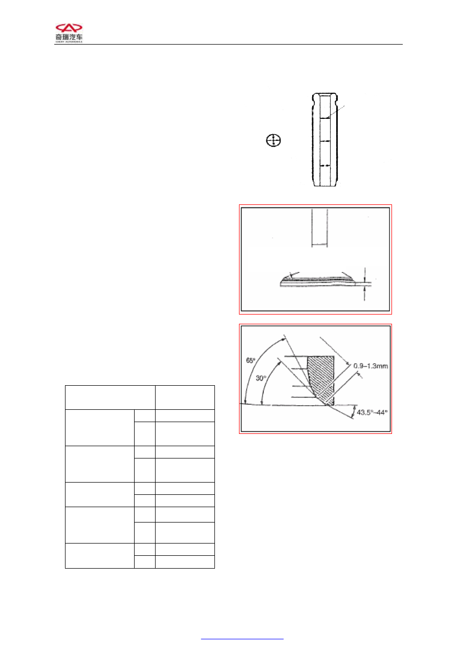
Examine  the  contact  bandwidth  of 
valve. 


e:


Check the valve seat insert. 


Standard 

Value 

IN 

¢5.98±0.008 

Outer Diameter 

of Valve stem 

(mm) 

EX 

¢5.96±0.008 

IN 

¢5.4±0.1 

Inner Diameter 

of Valve guide 

(mm) 

EX 

¢5.4±0.1 

IN 

0.02 

Clearance 

(mm) 

EX 

0.04 

IN 

0.3±0.15 

Thickness of 

Valve Top 

(mm) 

EX 

0.3±0.15 

IN 

1.158 

Seal Bandwidth 

(mm) 

EX 

1.306 


Measuring Point 


Contact Position (Should be 

the Center of Slope) 

Edge 

Thickness 


CHERY A21 SERVICE MANUAL


MECHANISM OF 2.0NALC ENGINE 

22 


f:


Examine  the  protruding  capacity  of 
valve stem. 

And  Examine  the  protruding  high  of  valve 
stem with vernier caliper.(See picture) 


Standard Value(mm)


Protruding Capacity 

Of Intake Valve 

stem 

47.5 

Protruding Capacity 

Of Exhaust Valve 

stem 

47.5 


5)


Examine the axial clearance of camshaft. 

Replace  the  camshaft  if  the  value  of  axial 
clearance exceeds the normal value. 


Standard Value 

Intake camshaft 

0.015—0.02 

Exhaust camshaft 

0.015—0.02 


6)


Examine the planeness of cylinder 

a:


Clear the lower surface of cylinder head. 

b:


With the  help  of  ruler  and  feeler gauge, 
check  whether  the  lower  surface  of 
cylinder  head  is  warped.(Measure  it  in 
the  sequence  of  A,  C,  D,  E,  F,  G  in  the 
picture) 


Standard 

Value 

Cylinder head planeness 

0.04 


Top of Valve Stem 

Protruding High of Valve Stem

Seat of Valve Spring 


CHERY A21 SERVICE MANUAL


MECHANISM OF 2.0NALC ENGINE 

23 


C:


Revise  it  if  the  planeness  exceeds,  and 
replace when it exceeds the limit value. 

The  permitted  maximum  abrading  thickness 
between cylinder block and cylinder head is: 

2.2.3


Installation 

The  installing  steps  are  reverse  to  those  for 
removal. 

Note: 

1)


Dismantle  valve  springs  into  groups. 
The  1st  and  4th  cylinders  are  in  one 
group  and  the  2nd  and  3rd  ones  are  in 
the  other  group.  Then  put  the  piston  to 
the  upper  point  of  1st  and  4th  cylinders 
in order to dismantle the valve spring of 
1st and 4th cylinders, replace their valve 
oil 

seal 

and 

mount 

the 

spring 

immediately.  And  put  the  piston  to  the 
upper  point  of  2nd  and  3rd  cylinders  in 
order to  replace  the  other  valve  oil  seal. 
Those  steps  prevent  from  that  the  valve 
falls  into  cylinder  and  the  unanticipated 
trouble occurs. 

2)


Wipe  the  engine  transmission  oil on  the 
opening  of  oil  seal  when  mounting  the 
valve oil seal. 

3)


Fasten the cylinder bolt as the following 
process. 

A:


Smear  some  oil  on  the  top  and  root  of 
bolt. 

B:


Fasten to 40±5NM in sequence. 

C:


Fasten 90±5 degree clockwise. 

D:


Fasten 90±5 degree clockwise. 


2.3  Replace thermostat 

2.3.1 

Structural diagram 

10 

CHERY A21 SERVICE MANUAL


MECHANISM OF 2.0NALC ENGINE 

24 


2.3.2  Needed tools and auxiliary materials 

Hatch clamp,10# sleeve, ratchet wheel and wrench 

2.3.3  Removal 

1) 

Loosen  the  clamp  of  thermostat  water  exhaust  pipe  with  hatch  clamp  to  release  the 
coolant. 

Note: Do it after the temperature decreased to prevent scald. 

2) 

Remove the 4 bolts of thermostat cover with 10# sleeve wrench. 

3) 

Take out the thermostat. 

2.3.4  Inspection 

Put  the  thermostat  in  the  boiling  water  and  use  it  with  thermometer.  Then  observe  the 
temperatures when the thermostat is turning on and fully opened. 


Temperature value 

Regular unlocking temperature 

87℃ 

fully opened temperature 

104℃ 

Replace the new thermostat if the measured value is abnormal. 

2.3.5  Installation 

The installing steps are reverse to those for removal. 

Note: Fill in the engine coolant with fixed quantity after installation.

1. Pad—Thermostat Seat 

2. Thermostat Seat 

3. Hexagonal Flange Bolt 

4. Thermostat Assembly 

5. Hexagonal Flange Bolt 

6. Cover—Thermostat Seat 


Content   ..  160  161  162  163   ..