Chery Fora (Elara A520). Manual - part 160
 

  Index      Chery     Chery Fora (Elara A520) - service repair manual


Search            


Content   ..  158  159  160  161   ..


Chery Fora (Elara A520). Manual - part 160


CHERY A21 SERVICE MANUAL


MECHANISM OF 2.0NALC ENGINE 

13 


2.4


Installation 

The  installing  steps  are  reverse  to  those  for 
removal. 

Note: Do engine timing. 

3.


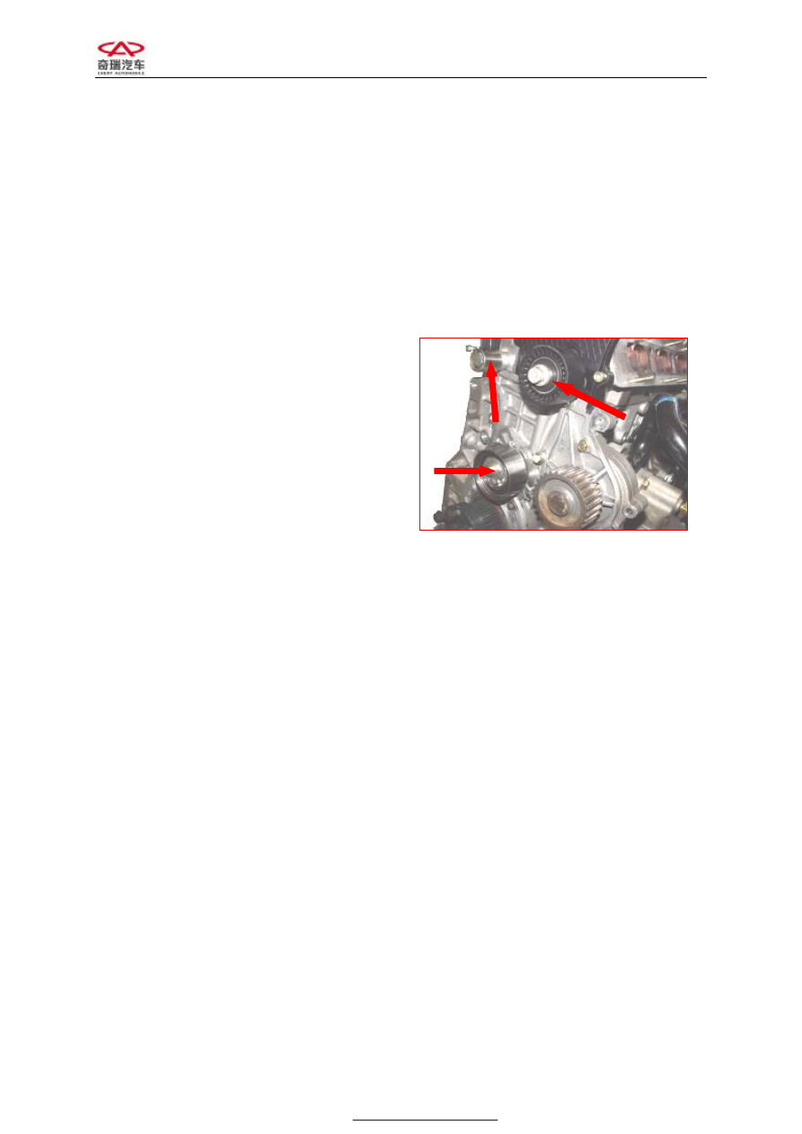
Replace  idler  wheel,  tensioner  and 
contact belt pulley   

3.1


Needed tools and auxiliary materials 

Allen  wrench,  10#,  13#  and  15#  sleeve, 
ratchet wheel and ratchet rod. 

3.2


Removal 

1)


Remove  the  timing  belt  (see  “replace 
timing belt” for details). 

2)


Remove  idler  wheel,  tension  pulley  and 
contact belt pulley.


3.3


Inspection 

1)


Check from appearance 

Check idler wheel, tension pulley and contact 
belt pulley carefully for any damages, such as 
sunken trace and sliding damage etc. 

2)


Check performance 

Revolve  tension  pulley,  idler  wheel  and 
contact belt pulley respectively to insure that 
they can run freely without stagnancy. 

Replace  it  with  the  spare  part  if  any  above 
problem is found. 

3.4


Installation 

1)


The  installing  steps  of  tension  pulley, 
idler  wheel  and  contact  belt  pulley  are 
reverse to those for removal. 

2)


Mount the timing belt and collate engine 
timing. 

3)


Mount other parts. 


CHERY A21 SERVICE MANUAL


MECHANISM OF 2.0NALC ENGINE 

14 

SECTION 2 CYLINDER HEAD 

I. STRUCTURAL DIAGRAM 


1. Gasket—Intake Manifold 

2. Intake Manifold Assembly 

3. Hexagonal Flange Bolt 

4. Throttle Valve Body Assembly 

5. Gasket—Throttle Valve Body Assembly 

6. Oil injector Assembly 

7. Fuel Distribution Pipe Assembly   

8. Bracket 

CHERY A21 SERVICE MANUAL


MECHANISM OF 2.0NALC ENGINE 

15 


1. Intake Valve   
2. Valve Oil Seal 
3. Valve Spring Seat 
4. Valve Spring 
5. Valve Spring Retainer 
6. Keeper   
7. Exhaust Valve 
8. Intake Camshaft Assembly 
9. Bearing Cap Assembly   
10. Control Valve-Camshaft Phaser Assembly 
11. First Bearing Cap Assembly 

12. Front Camshaft Oil Seal 
13. Exhaust Camshaft Assembly 
14. Rocker Arm Assembly 
15. Hydraulic Tappet Assembly 
16. Stud Bolt (9 Bars) 
17. Cylinder Head Gasket   
18. Temperature Sensor 
19. Engine Hanger 
20. Cylinder Head Bolt 
21. Cylinder Head Assembly 

11 

15 

14 

13 

10 

17 

18 

12 

16 

19 

20 

21 

CHERY A21 SERVICE MANUAL


MECHANISM OF 2.0NALC ENGINE 

16 


II. MAINTENANCE 

2.1


Replace  intake  manifold,  delivery pipe 
and oil injector 

2.1.1


Needed tools and auxiliary materials   

Ratchet  wheel,  ratchet  rod,  10#  sleeve  and 
crosshead screwdriver 

2.1.2


Process of removal 

1)


Put the ignition key at the OFF position. 

2)


Loosen the plug of oil injector. 


3)


Remove  the  connecting  bolt  between 
engine oil dipstick and intake manifold.   


4)


Remove  the  clamp  between  intake  hose 
and throttle valve body. 


5)


Remove  the  connecting  bolt  of  throttle 
valve  body,  and  take  out  throttle  valve 
body. 

Note:  Because  this  throttle  valve  body  is 
electronic,  do  not  force  the  middle  vanes 
turning manually or with other objects. 


6)


Loosen the joint of oil intake pipe. 


7)


Remove  the  fastening  nut  of  intake 
manifold  and  take  out  the  intake 
manifold. 


Content   ..  158  159  160  161   ..