Chery Fora (Elara A520). Manual - part 144
 

  Index      Chery     Chery Fora (Elara A520) - service repair manual


Search            


Content   ..  142  143  144  145   ..


Chery Fora (Elara A520). Manual - part 144


CHERY·A21 SERVICE MANUAL                                  ENGINE EFI SYSTEM 

15 

(Disassemble 

the 

joint)leave 

the 

digital 

multimeter  at  ohm  shift  and  contact  the  No.1 
and  No.  2  pin  of  the  sensor  by  its  two  meter 
pens.  When  it  is  20

Rated

  the  resistance  is 

2.5kΩ±5%.  The  other  temperature  can  get 
reference from above chart. 

3.3 KNOCK SENSOR 

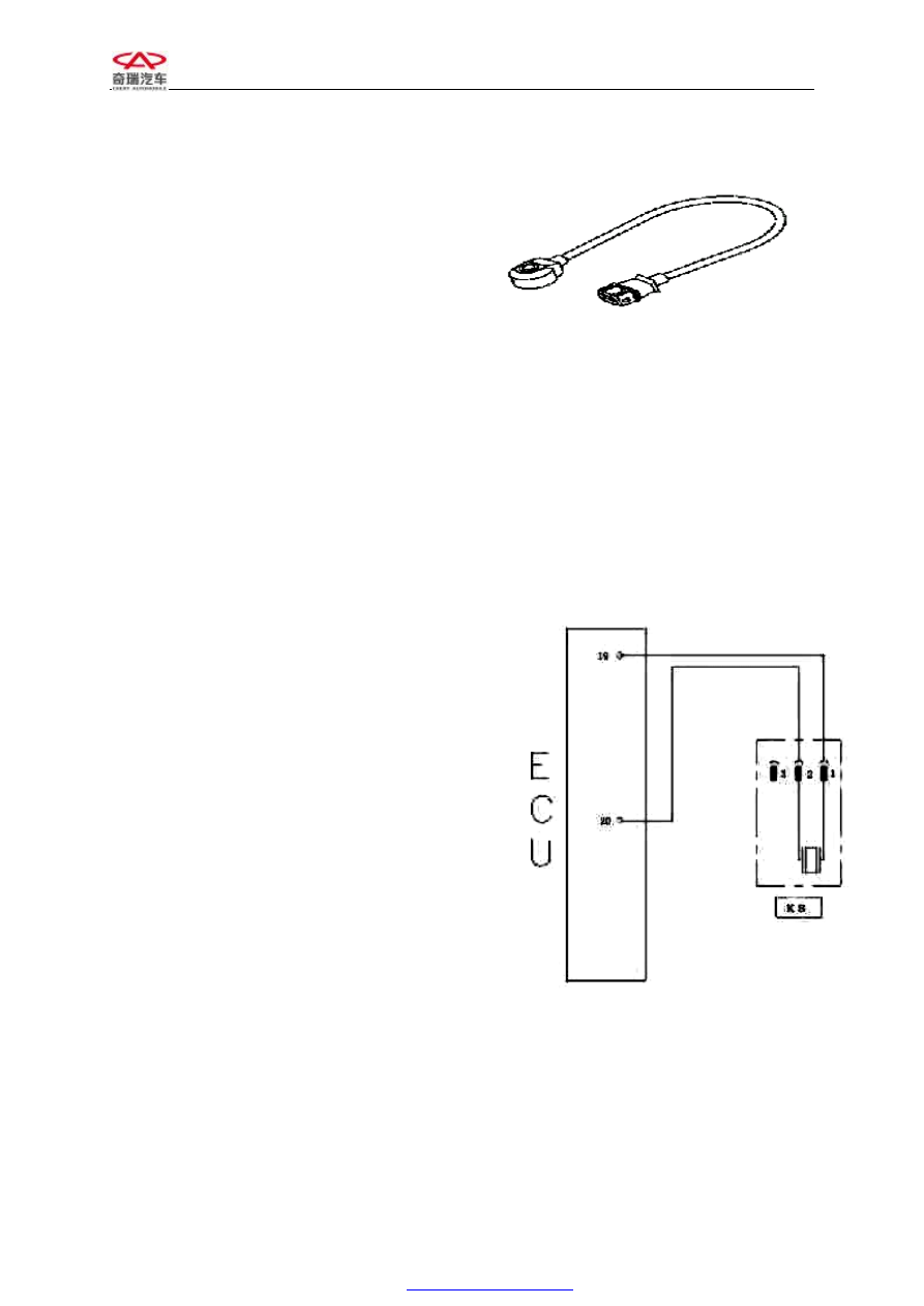
1)Exterior drawing and pin 

This  sensor  has  three  pins;  No.1  and  No.2  pin 
connect with ECU, and No. 3 pin connects with 
shield. 

2)Purpose:  This  sensor  provides  engine 

knock  information  to  ECU,  and  carries 
out knock control.
 

3)Installation position 

There  is  a  hole  in  the  middle  of  knock  sensor, 
and  the  sensor  is  assembled  on  the  block 
between  No.2  and  No.3  cylinder  head.  For  the 
aluminum  alloy  block,  using  long  bolt  with 
30mm  long;  for  the  casting  iron,  using  25mm 
long bolt. And the moment is 20±5Nm. 

4)Working principle 

Knock sensor is a kind of vibrating acceleration 
sensor  and  is  assembled  on  cylinder  block. The 
sense  organ  of  the  sensor  is  a  piezoelectric 
element.  The  vibration  of  cylinder  block  is 
transferred  to  piezoelectric  crystal  by  mass 
block  inside  of  sensor.  The  piezoelectricity 
crystalloid  gets  pressure  from  mass  block 
vibration,  producing  voltage  on  two  polar  and 
transferring  vibration  signals  to  voltage  signal 
and  output  it.  Because  the  frequency  of  knock 
vibration  signal  is  much  higher  than  the normal 
engine  vibration  signal,  the  ECU  can  separate 
the  signal  into  knock  signal  and  non  knock 
signal. 

5)Normal working temperature: -40--130℃ 

6)Malfunction  phenomenon  and  diagnosis 

method 

Chart 3-4    Exterior drawing of knock 

sensor 

Chart 3-5 circuit diagram of knock 

sensor 

Knock sensor 

CHERY·A21 SERVICE MANUAL                                  ENGINE EFI SYSTEM 

16 

l  Malfunction 

phenomenon: 

badness 

accelerating. 

l  Normal  malfunction  reason:  all  kinds  of 

liquid  such  as  oil,  coolant,  braking  liquid 
and  water  contact  with  sensor  for  a  long 
time and erode the sensor. 

l  Simple measuring method: (disassemble the 

joint)  put  digital  multimeter  at  ohm  shift, 
and  contact  the  No.1,  No.  2  and  No.3  pin 
with  its  two  meter  pens.  The  resistance 
value  should  be  more  than  1MΩ  at  normal 
conditions.  Leave  the  digital  multimeter  at 
millivolt  shift,  and  tap  around  the  sensor 
using little hammer, there should be voltage 
signal output. 

3.4 OXYGEN SENSOR 

1)Exterior drawing and pin 

There are 4 pins on this oxygen sensor 

No. 1 connect to heating power anode (white) 

No. 2 connects to heating power cathode (white) 

No. 3 connects to signal cathode (gray) 

No. 4 connects to signal anode (black) 

2)Installation position: Assemble it on the top 

of exhaust pipe. 

3)Purpose:  The  oxygen  sensor  checks  the 
oxygen percent in exhaust gases and transfer the 
signal  to  ECU,  and  ECU  will  control  the  fuel 
closed  loop  according  to  this  information.  This 
will  make  engine  working  at  its  optimum 
conditions.  And  transfer  and  purify  CO,  HC, 
NO

compound  in  3-way  catalytic  converter  of 

the tail gas maximally. 

4)Working principle 

Sensing  element  of  oxygen  sensor  is  a  kind  of 
ceramic  tube  with  holes,  and  outside  of  tube 
walls are surrounded by engine exhaust gas and 
inside is air. Ceramic sensor element is a kind of 
solid state electrolyte with electrical heating   

Chart 3-6 Exterior drawing of oxygen 

sensor 

Oxygen sensor 

Main relay 

Chart 3-7 circuit diagram of oxygen 

sensor 

CHERY·A21 SERVICE MANUAL                                  ENGINE EFI SYSTEM 

17 

tube  inside.  The  working  of  oxygen  sensor  is 
carried  out  by  transferring  the  concentration 
difference  of  the  oxygen  ion  outside  of ceramic 
tube  to  voltage  (100mv—900mv)signal  and 
output. 

5)Working voltage:12—14V 

6)Malfunction and diagnosis method 

l  Malfunction:  badness  idle  speed,  badness 

acceleration,  badness  tail  gas,  over  fuel 
consume etc. 

l  Reason:  1,  moisture  entering  inside  of 

sensor,  and  when  the  temperature  is 
changed 

pin 

is 

broken; 

2, 

sensor 

poisoning( Pb,S,Br,Si) 

l  Notice: it is forbidden to use cleaning liquid, 

oiliness  liquid  or  volatility  solid  during 
service. 

l  Measuring  method:  a)  disassemble  joint, 

put digital  multimeter to ohm shift, connect 
meter  pen  to  No.1(white)  and  No.2(white) 
pins  of  the  sensor.  Normally  the  resistance 
value  is  1~6Ω.  b)  Connect  the  joint  and 
keep  it  at  idle  speed  status.  When  the 
oxygen  sensor  reaches  to  its  working 
temperature  350℃,  keep  digital  multimeter 
to  DC  volt  shift  and  connect  meter  pen  to 
No.3 (gray) and No.4 (black) pins of sensor. 
Now  the  voltage  should  be  fluctuate 
between  0.1-  0.9V  quickly  (the  data  also 
can  be  gotten  from  data  flow  inspected  by 
diagnosis meter). 

3.5 SPEED 

SENSOR 

(CRANKCASE 

POSITIONING SENSOR) 

1)Exterior drawing and pin 

No.1pin connects to shield 

No.2 and No.3 pin provide signal to ECU. 

2)Installation  position:  on  the  flywheel  plane 

at rear of engine. 

Chart 3-8 Exterior Drawing Of Speed 

Sensor 

CHERY·A21 SERVICE MANUAL                                  ENGINE EFI SYSTEM 

18 

Service notice: 

l  For the  inductive engine speed sensor, it is 

permitted to take out from its pack before it 
is  assembled  to  the  auto  or  testing  device 
right away. 

l  Inductive engine speed sensor is assembled 

by press in method but not hammer tapping. 

l  Tightening  torque  is  8.2Nm.  Gas  clearance 

between  inductive  engine  speed  sensor  and 
pulse disc is 0.8 - 1.2mm. 

3)Purpose: Speed sensor provides engine speed, 
crankshaft  angle  and  top  dead  center  signal  to 
ECU.  That  will  control  engine  ignition  and 
injection timing. 

4)Working  principle:  The  inductive  engine 
speed sensor work together with pulse disc, it is 
used  in  ignition  system  without  distributor 
providing engine speed and crank shaft top dead 
center  information.  Speed  sensor  is  made  up  of 
a permanent magnet and coil outside of magnet. 
Pulse disc is a tooth disc with 60 teeth originally 
but  there  are  two  teeth  opening.  Pulse  disc  is 
assembled  on  crank  shaft  and  rotate  with 
crankshaft. When the tip of the tooth passed the 
end  of  inductive  engine  speed  sensor,  the 
magnet  pulse  disc  incises  the  magnetic  line  of 
force,  generating  rotating  speed  signal  and 
output. 

5)Working temperature:-40--120℃ 

Resistance of coil in room T:731--989Ω


6)Malfunction and diagnosis method: 

l  Malfunction: can not start etc. 

l  Reason: man failure 

l  Service notice: use pressing method but not 

a hammer to install it. 

l  Simple  measure  method:  disconnect  the 

joint,  put  digital  multimeter  to  ohm  shift, 
connecting two meter pen to No. 2 and No. 

Speed sensor 

Chart 3-9 Circuit diagram of speed 

sensor 


Content   ..  142  143  144  145   ..