Chery Fora (Elara A520). Manual - part 54
 

  Index      Chery     Chery Fora (Elara A520) - service repair manual


Search            


Content   ..  52  53  54  55   ..


Chery Fora (Elara A520). Manual - part 54


CHERY A21 SERVICE MANUAL


MECHANISM OF 2.0NALC ENGINE 

19 


2.1.3


Installation steps 

The installing steps are reverse to those for 
removal. 

2.2


Replace camshaft, bearing bushings, 
valve and valve oil seal. 

2.2.1


Needed tools and auxiliary materials 

Special tools for valve oil seal, engine 
transmission oil, a set of sleeve tools, an 
adjustable spanner, special tools for timing 
and a set of Allen wrenches 

2.2.2


Removal 

1)


Remove the dynamo belt (see “removal 
of dynamo belt” for details). 

2)


Remove the timing belt (see 
“replacement of engine timing belt and 
timing calibration” for details). 

3)


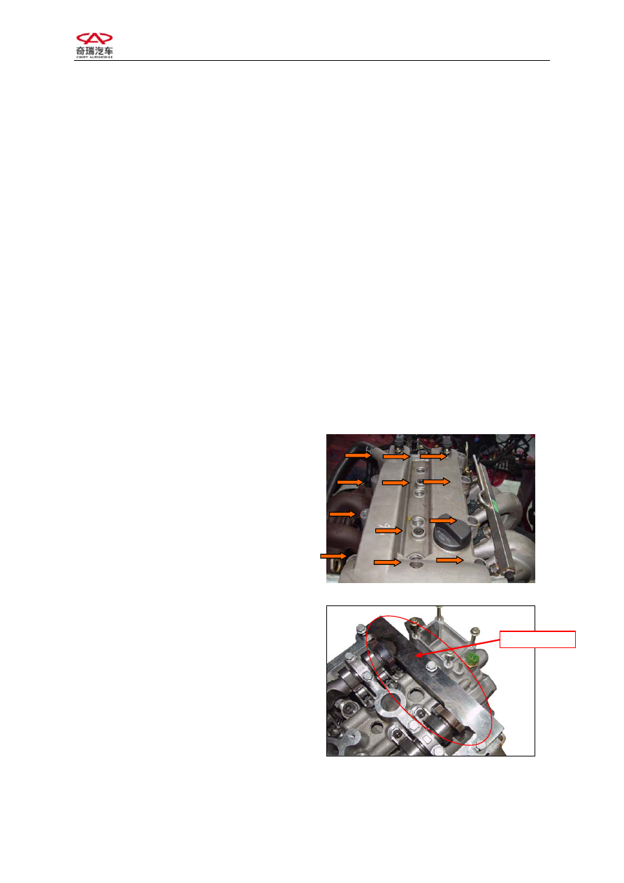
Remove the cover of engine valve 
chamber. 


4)  Clamp the timing special tool into 

camshaft slot and fasten the bolt. 


Camshaft Tool 


CHERY A21 SERVICE MANUAL


MECHANISM OF 2.0NALC ENGINE 

20 


5)  Dismantle the belt pulley of air intake 

and exhaust camshafts with torque 
wrench. 


6)  Remove the back cover of timing belt. 


7)  Dismantle the bearing caps of air intake 

and exhaust camshaft respectively and 
put them down in the sequence. 

Note: The second, third, fourth and fifth 
camshaft bearing caps are marked with I1, I2, 
I3, I4 (E1, E2, E3, E4), which stands for the 
corresponding bearing cap of 1, 2, 3, 4 
cylinder respectively. (“I” refers to intake 
camshaft, “E” refers to exhaust camshaft). 

Torque: 


CHERY A21 SERVICE MANUAL


MECHANISM OF 2.0NALC ENGINE 

21 

See the following picture for removal sequence of intake and exhaust camshaft-bearing caps: 


8)  Take out the camshaft and the hydraulic tappet. 

9)  Remove the valve spring with special tools. 

(Picture is unavailable)


10)  Remove the used valve oil seal with special tools. 

(Picture is unavailable) 

2.2.3

 Inspection


1)


Check the valve spring. 

Measure the free length, the verticality and 
the length under special pressure with caliper. 


Standard 

Value(mm)

Free length 

47.7 

Length of 

620N 

32 

Replace with the new valve spring if the 
measured value exceeds the limit value. 


CHERY A21 SERVICE MANUAL


MECHANISM OF 2.0NALC ENGINE 

22 


2) Check 

camshaft 

Measure the camshaft diameter with 
micrometer caliper. 


Standard Value

(mm) 

Limit Value 

(mm) 

Diameter 

¢24

-0.053

-0.040 


Replace with the new camshaft if the 
measured value exceeds the limit value.


3) Examine 

camshaft 

Measure the high of cam with micrometer 
caliper. 


Standard Value

(mm) 

limit value

(mm) 

Intake 

Cam 

37.15 


Exhaust 

Cam 

37.05 


Replace with the new camshaft if the 
measured value exceeds the limit value.


4)  Examine diameter of valve stem 

a:  Measure the diameter of valve stem with 

micrometer caliper. 

See the picture for measuring points: they are 
26, 52, and 78 mm from measure positions to 
bottom of valve. 


Valve 

Guide 

External Diameter

Of Valve Stem 

Internal Diameter 

Of Valve Guide 


Measuring Point 


Content   ..  52  53  54  55   ..