Chery Fora (Elara A520). Manual - part 43
 

  Index      Chery     Chery Fora (Elara A520) - service repair manual


Search            


Content   ..  41  42  43  44   ..


Chery Fora (Elara A520). Manual - part 43


31 


4)


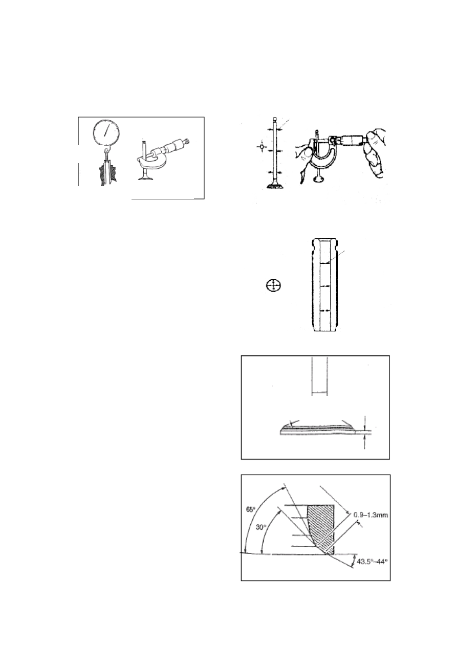
Check the diameter of value stem   

a:


Use  micrometer  caliper  to  measure  the 
diameter of valve stem. 


B:


Use  inner  micrometer  guage to  measure 
the inner diameter of valve guide. 

C:


Calculate  the  difference  of  measured 
value and the clearance.   

If  they  exceed  the  specified  limit  values, the 
value  or  guide  shall  be  replaced  more 
necessarily. 


D:


Check the contact bandwidth of valve. 


E:


Check the valve seat insert. 


Valve 

Guide 

Outer Diameter 

Of Valve Stem 

Inner Diameter Of 

Valve Guide 


Measuring Point 


Measuring Point 


Contact Position (Should Be 

At The Center Of Slope.) 

Edge 

Thickness 


32 


Standard 

value 

Limit 
value 

Outer diameter 

of valve stem 

(mm) 

IN 

¢5.98±0.008 


EX 

¢5.96±0.008 


Inner diameter 

of valve guide 

(mm) 

IN 

¢5.4±0.1 


EX 

¢5.4±0.1 


Clearance 

(mm) 

IN 

0.02 


EX 

0.04 


Thickness of 

value top 

(mm) 

IN 

0.3±0.15 


EX 

0.3±0.15 


2.2.3


Installation 

The  installing  steps  are  reverse  to  those  for 
removal. 

Note: 

1)


Dismantle  the  valve  springs  in  two  groups 
with  1st  and  4th  cylinders  in  one  group,  2nd 
and  3rd  cylinders  in  the  other  group.  When 
the  piston  runs  tothe  top  dead  center  of  1st 
and  4th  pistons,  you  should  dismantle  the 
valve  springs  of  the  1st  and  4th  cylinders, 
replace  the  valve  oil  seal,  and  mount  valve 
springs  immediately.  When  the  piston runs to 
the  top  dead  center  of2nd  and  3rd  cylinders, 
you  should  replace  the  valve  oil  seal.  Thus, 
you  can  prevent  the  valve  from  falling  into 
the cylinders, reducing unnecessary troubles.   

2)


Apply  engine  lubricant  onto  the  oil  seal  lip 
when installing the valve oil seal.


33 

SECTION II INTRODUCTION TO NEW ENGINE   

TECHNOLOGIES——CBR& VVT 

1. CBR PROFILE 

CBR principle and structure 

By  controlling  the  organization  modes  of  air 
flow  (eddy  flow  and  turbulent  flow),  CBR 
(Controlled Bum Rate) can  improve the burn 
rate,  reduce  displacement,  and  boost  the 
economical efficiency of fuel. 


This engine adopts sliding plate CBR. 


●  When  the  engine  operates  at  low  speed, 

the vacuum actuator shall drag the sliding 
plate  to  move  towards  the  direction 
shown  in  the  figure  by  use  of  rocker 
assembly,  and  the  neutral  air  passage 
shall  be shut off basically (there  is only  a 
gap  on  the  top  right  corner).  The  mixing 
of oil mist and air  mainly depends on the 
eddy  flow  of  air  intake  provided  by 
tangential  air  duct,  thus  improving  the 
combustion status.   

●  When  the  engine  operates  at  high  speed, 

CBR  control  valve  shall  cut  off  the 
vacuum  condition  of  vacuum  actuator; 
thanks to the spring  functions, the sliding 
plate  shall  return  to  the  position 
illustrated  in  the  figure,  and  the  neutral 
air  duct  shall  also  be  opened,  which 
increases  the  turbulent  flow  of  air  intake 
and improve the maximum power. 


Structure of sliding plate 

1)  Sliding plate 

2)  Rocker and shaft assembly   

3)  Bracket 

4)  Vacuum actuator 


Tangential Air Duct 

Neutral Air Duct 


34 

2.VVT PROFILE 

VVT Principle 

VVTi  is  the  abbreviation  of  variable  valve  timing  with  intelligent.  During  the  operation  of 
engine,  the  valve  opening  time  is  called  as  valve  timing.  When  the  engine  operates  at 
different rotation speeds, we need different valve timings to provide the optimal valve closing 
control,  so  that  the  power  and  combustion  efficiency  can  achieve  the  best  effect.  For  this 
purpose, we shall  install VVTi  mechanism onto the camshaft controlling the air  intake valve 
to regulate  valve  timing.  The  VVTi  system  installed on  the  air  intake  camshaft  of engine  is 
equipped with oil- pressure clutch device between the camshaft and drive sprocket, which can 
alter  the  rotation  phase  difference  between  the  air  intake  camshaft  and  drive  sprocket.  The 
controlled oil pressure mechanism connects with the engine oil system, and can be regulated 
by  solenoid  valve  and  control  loop.  When  the  engine  operates  at  different  rotation  speeds, 
there are different angles  between the camshaft and sprocket, which  facilitates the air  intake 
valve to open and close at different times in an effort to achieve variable valve timing. On the 
other  hand,  when  the  engine  operates  at  different  rotation  speeds,  abundant  and  appropriate 
oil gas can be supplied to generate mighty power. 

When the car engine  equipped with VVT-I system  fails abnormally, ECUs controlled  by the 
engine  shall  automatically  lock  the  preset  parameter  value  (come-home  function),  ensuring 
the  driver  to  drive  the  car  to  the  maintenance  station.  This  kind  of  engine  lodges  a  strictly 
demand  for  the  quality  of  petroleum  and  lubricant;  therefore,  you  must  adopt  the  standard 
materials  in  compliance  with  the  stipulations  of  original  car  manufacturer  in  order to  avoid 
unnecessary damages. 


Content   ..  41  42  43  44   ..