Chery Fora (Elara A520). Manual - part 26
 

  Index      Chery     Chery Fora (Elara A520) - service repair manual


Search            


Content   ..  24  25  26  27   ..


Chery Fora (Elara A520). Manual - part 26


Chery Service Manual for A520                Body Dimension and Accessories


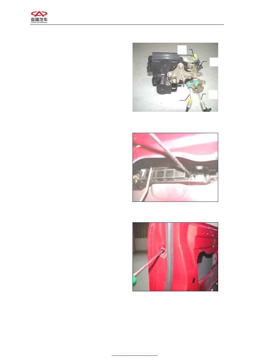
18.  The  latch  mechanism  is  as shown  in the 

figure: 

A:  Locking cable 

B:  Opening out control cable 

C:  Link the opening out push rod 

D:  Link the latch pull rod


Figure 62


19.  Unscrew the door handle bolt 1;


Figure 63


20.  Unscrew the bolt 2;


Figure 64


Chery Service Manual for A520                Body Dimension and Accessories


21.


Take out the door handle; 

A:


Latch pull rod 

B:


Opening out push rod 

C:


Latch  (could  be  replaced  directly  on  the 

vehicle)


Figure 65


22.


Remove the door check; 

Assembly  requirements:  The  tightening 
torque  for  the  bolt  is  7.2±0.7N·m  and  the 
value  is  25±3  N·m  while  mounted  on  the 
door  pillar  and  9±1  N·m  while  mounted  on 
the door. The door check should work easily, 
reliable  without  being  hit  and  stuck.  Grease 
should  be  applied  into  the  room  between  the 
pull rod and the slider of the door check.


Figure 66


23.


Remove the weather strip  from the door 
opening; 

During  installation,  every  corner  should  be 
fitted  in  place  and  no  folds  are  allowed. The 
joint of weather strip should  be placed in the 
lower  middle  of  the  door  opening.  The 
weather  strip  should  have  a  proper  rigidity 
and should not interfere with the opening and 
closing  of  the  door  after  the  lock  and  hinge 
have  been  adjusted  to  the  operating  mode. 
The  hardness  of  the  weather  strip  should  be 
proper  without  great  variation  with  the 
temperature  changes.  The  surface  of  the 
assembled  rubber  strip  should  not  have  any 
defects 

such 

as 

hammering 

imprint, 

deformation and warp etc. 


Figure 67


Chery Service Manual for A520                Body Dimension and Accessories


24.


Remove the glass run; 


Figure 68


25.


The  inner  harness  of  the  door  could  be 
taken out from outside;


Figure 69


II. DISASSEMBLING THE REAR DOOR 

See  left  front  door  for  considerations 
during disassembling the parts 

1.


Remove  the  trim  strip  from  the  left  rear 
door;


Figure 70


Chery Service Manual for A520                Body Dimension and Accessories


10 


2.


Unscrew  the  screws  to  detach  the  inner 
and  outer  trim  panels  of  the  triangle 
glass;


Figure 71


3.


Unscrew the screw to detach the bezel for 
the inside door handle;


Figure 72


4.


Unscrew the screw to detach the arm rest 
cover;


Figure 73


Content   ..  24  25  26  27   ..