Chery B11. Manual - part 218


  Index      Chery     Chery B11 - service repair manual


Search            


Content   ..  216  217  218  219   ..


Chery B11. Manual - part 218


Chery·Maintenance Manual for Oriental Son


Automatic Transmission 

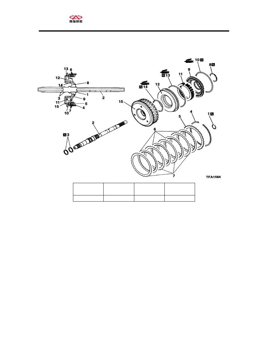
Components of Underdrive clutch and 

put Shaft 


Clutch plate

Clutch disc

Reaction 

plate 

In


Type 

F4A42 


4 4 1 

1. Snap ring 


on plate 


9. Spring hub 

ring 

 piston 


2. Input shaft
3. Seal ring 
4. Snap ring 
5. Clutch reacti

e

6. Clutch plat
7. Clutch disc 
8. Snap ring 

10. D seal ring 
11. Offsetting sp
12. Underdrive clutch
13. D seal ring 
14. D seal  ring 
15. Underdrive clutch bracket 


40 


Chery·Maintenance Manual for Oriental Son


Automatic Transmission 


Com

one
ts

ever

-gear and Overdrive Clutch 


Type 

Clutch plate

p
n  of 
R
se


plate 


Clutch disc

Reaction 

F4A42 4 4 1 
Reverse-
gear clutch 

2 2 1 

1. Snap ring 
2. Clutch reaction plate 
3. Clutch plate 
4. Clutch disc 
5. Snap ring 
6. Clutch reaction plate 
7. Clutch plate 
8. Clutch disc 
9. Pressure plate (F4A5) 
10. Snap ring 
 

11
12
13
14
15
16
17
18
19
20

. Spring hub 
. D seal ring 
. Offsetting spring 
. Overdrive clutch piston 
. D seal ring 
. Reverse-gear clutch piston 
. D seal ring 
. Reverse-gear bracket 
. D seal ring 
. D seal ring 

41 


Chery·Maintenance Manual for Oriental Son


Automatic Transmission 


Part Two: Hydraulic System 

Disassembly and assembly of valve body 

isassembly of inner valve body 
ote:  

ake care not to change component positions. 

any valve bodies, seal washers and steel 

alls resemble each other but would cause 
amage to the gearbox if they are wrongly 

ou are not going to get confused up.  

olenoid valve:  

. Mark on each solenoid valve to distinguish 

eir positions. The left figure shows the 

osition of solenoid valves and the following 

ble makes a description: 

ark Name 


D
N
T
M
b
d
installed. Please arrange them in order so that 
y
S
1
th
p
ta
M
#1 

Underdrive solenoid valve 

#2 

Second-gear solenoid valve 

#3 

Damp clutch control solenoid valve

#4 

Overdrive solenoid valve 

#5 

Low/reverse-gear solenoid valve 

2. Unfix wire harness, bracket and set bolts of 

e solenoid valve.  

. Unfix underdrive solenoid valve 
. Unfix second-gear solenoid valve 
. Unfix the control solenoid valve of damp 

lutch.  

. Unfix the overdrive solenoid valve. 
. Unfix the low/reverse-gear solenoid valve. 
. Unfix the manual valve.  
. Unfix the four set bolts on outer valve tank, 

ire harness bracket and outer valve cover.  

0. Separate the inner and outer valve bodies.  
1. Unfix outer valve body plate 
2. Unfix three steel balls.  

eel ball springs. 

d set bolts.  

6. Unfix the shock absorber spring 

7. Unfix the steel balls for release of pipeline 

eel ball.  

th
3
4
5
c
6
7
8
9
w
1
1
1
13. Unfix two st
14. Unfix valve body plate an
Shock absorber 
15. Unfix the shock absorber 
1
 

1
pressure.  
18. Unfix the spring.  
19. Unfix the throttle st
20. Unfix the spring.  


steel 
ball

Steel ball 
and spring

shock absorber

Steel ball 

and spring

shock absorber

Steel ball

and spring

42 


Chery·Maintenance Manual for Oriental Son


Automatic Transmission 


Fail-safe valve 

1. Unfix the retainer plate. 
2. Unfix the sleeve of fail-safe valve-B 
3. Unfix the fail-safe valve-B 

djusting valve 

4. Dismantle the retainer plate 
5. Screw out the bolt 
6. Unfix the spring of adjusting valve. 
7. Unfix the pressure-adjusting valve. 

ail-safe valve-A 

8. Unfix the retainer plate 
9. Unfix the sleeve of fail-safe valve-A 
0. Unfix the fail-safe valve-A2 
1. Unfix the spring of fail-safe valve A 
2. Unfix the fail-safe valve-A1 

ydraulic torque converter 

ix the faucet 

lve.

 of hydraulic torque 

lutch 

9. Unfix the control valve of damp clutch 
0. Unfix the spring of control valve of damp 

lutch.  

ote:  

efore assembly, please apply ATF on all 

ner components.  

amp clutch valve 

. Fix the spring of damp clutch control valve 

2
2
2


A
2
2
2
2


F
2
2
3
3
3
 
 
H
33. Unfix the retainer plate 
34. Unf
35. Unfix the hydraulic torque converter va
36. Unfix the spring


converter 
Damp clutch valve 
37. Unfix the roller.  
38. Unfix the sleeve of control valve of damp 
c
3
4
c


Assembly of inner valve body 
N
B
in
D
1

Retainer 
plate 

Save valve 

Sleev of save 
valve B

Retainer 
plate

lt 

Bo

Adjusting 
valve

Retainer 
plate

Sleeve of fail-
safe valve-A

Save valve-A2 

Safe valve spring

Safe valve-A1 

Retainer 
plate

Faucet 

Hydrraulic 

Converter valve 

Roller 

Damp clutch 

l

Valve spring 

43 


Content   ..  216  217  218  219   ..