Chery B11. Manual - part 93


  Index      Chery     Chery B11 - service repair manual


Search            


Content   ..  91  92  93  94   ..


Chery B11. Manual - part 93


bad contact, improper grounding circuits or 
any other troubles relating to the ignition 
switch.  

13 

Repair the high resistance source between 
Terminal C and car body grounding circuit. 
Identify and check the grounding location 
after the car body is well grounded.  


14 

Repair the high resistance source between 
Terminal B6 and DLC Terminal 7.  


15 

Identify and repair the ground fault circuit of 
the data circuit.  


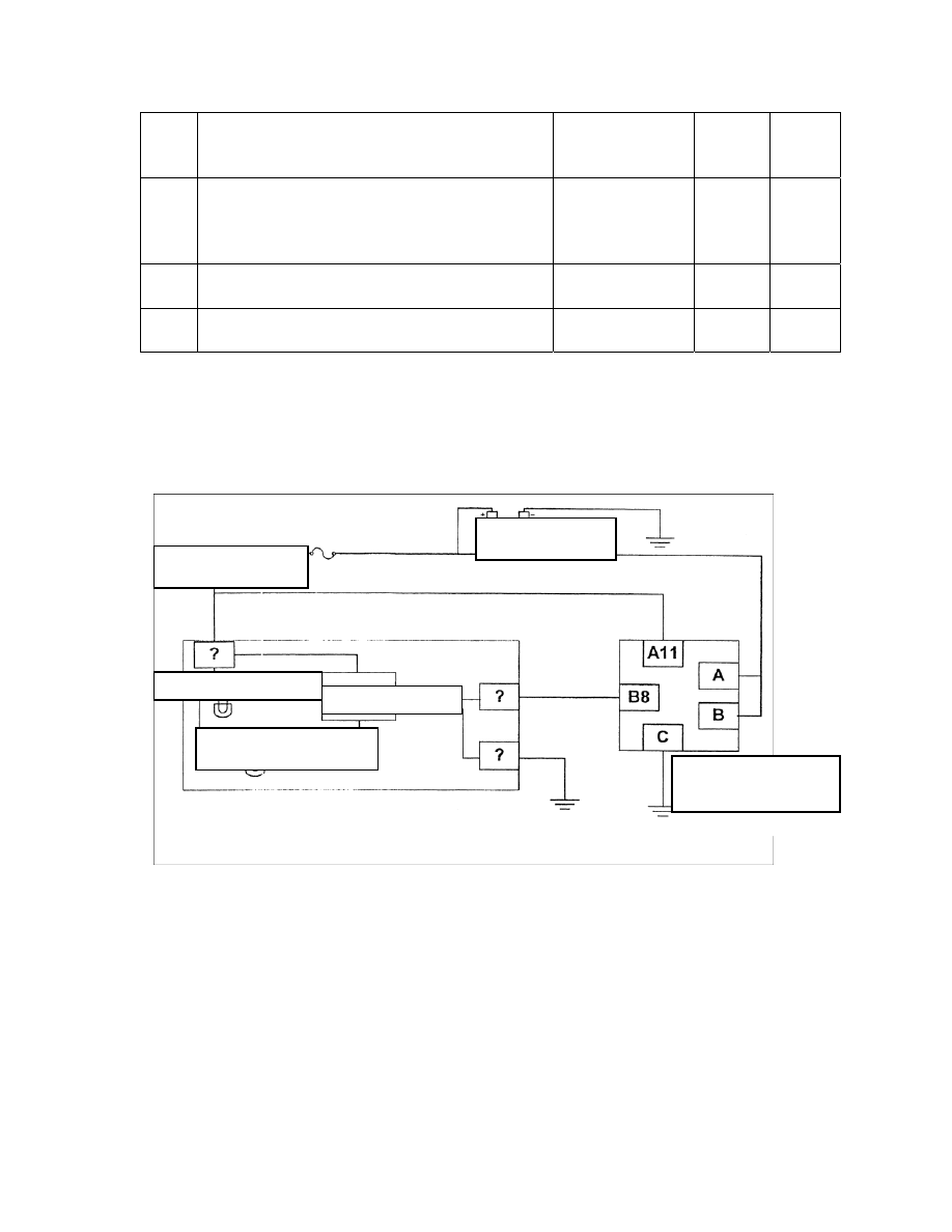
Two. Failure of ABS alarm lamp/absence of troubleshooting code setup 


Power supply 


Ignition switch 


ABS alarm lamp

Light module


Braking alarm lamp 


Electronic brake 
control module 


1. Description of circuit 
The EBCM controls the orange ABS 
alarm lamp through the driver lamp 
module incorporated in the instrument 
panel.  
When the ignition lamp is on, the battery 
provides voltage to Terminal ? of the 
instrument panel and EBCM Terminal 
A11. EBCM Terminals A and B are 
always electrified.  

Default status refers to the turning on of 
the orange ABS module alarm lamp 
through the driver lamp module. The 
driver lamp module provides the path for 
grounding. 
When the EBCM instructs the ABS 
alarm lamp to turn off, the EBCM will 
ground the ABS alarm lamp control 
circuit, which will cause the driver lamp 
module to provide path for the lamp’s 
grounding.  

When the ignition switch is on, the 
EBCM will turn on the ABS alarm lamp 
for three seconds for bulb checking. 
Once any ABS trouble is detected, the 
EBCM will turn on the ABS alarm lamp 
to inform the driver of the trouble.  


2. Assistance to troubleshooting 
The typical causes of the failure of ABS 
alarm lamp and the absence of 
troubleshooting codes include:  
ABS lamp trouble/socket bad contact 
Broken fuse on instrument panel 
Instrument panel/driver lamp module 
trouble 

EBCM trouble 
The circuit between EBCM and 
instrument panel is grounded 


3. Diagnostic step


Step Diagnostic 

action 

Expected 
value 

Yes No 

If checking of diagnostic circuit has been finished 


To 
Step 2 

To Step 

1. Detach the EBCM wire harness from the EBCM. 
2. Ignite 
Is the orange ABS lamp on? 


To 
Step 9 

To Step 

1. Check instrument fuse 
2. Is the contact between fuse and terminal all right?  


To 
Step 4 

To Step 
10 

1. Shut off engine 
2. EBCM wire harness remains detached 
3. Dismantle the instrument assembly from the 
instrument panel. 
4. Detach the (color) instrument wire harness connector 
from the instrument assembly 
5. Ignite 
6. Connect the voltmeter to the instrument wire harness 
Terminal ?13 foot power source (color) and then to the 
car body for grounding. 
Is the voltage within the range required?  

Battery 
voltage 

To 
Step 5 

To Step 
11 

1. Shut off engine 
2. The white instrument wire harness and EBCM wire 
harness are still detached from each other.  
3. Connect one ohmmeter between color instrument wire 
harness Terminal 14 and EBCM wire harness Terminal 
B8.  

2 Ω 

To 
Step 6 

To Step 
12 

Is the resistance within the range required? 

Dismantle the orange ABS lamp from the instrument and 
check if there is any broken filament or bad contact of 
socket.  
Are the socket and lamp all right?  


To 
Step 7 

To Step 
13 

Replace instrument assembly 

OL (open 
circuit) 

To 
Step 8 

To Step 
14 

Check the diagnostic circuit 


Replace the EBCM 


10 

Replace the broken fuse and/or repair loosened terminals. 
Find the short circuit that causes the broken fuse if 
possible.  


11 

Identify and repair the causes for undervoltage of 
instrument power source 


12 

Identify and repair the ground fault circuit between 
instrument panel and electronic brake dynamic control 
module wire harness 


13 

Replace bulb/socket as the case may require 


Three. ABS alarm lamp beaming/absence of troubleshooting codes setup 
 

. Description of circuit 

 orange ABS 

e ignition lamp is on, the battery 

provides voltage to Terminal ? of the 

instrument panel and EBCM Terminal 

lamp module. The 

Power supply

Ignition switch 

1

ABS alarm lamp 

1

Light module

Braking alarm lamp 

1

Electronic 
brake control 
module 

1
The EBCM controls the
alarm lamp through the driver lamp 
module incorporated in the instrument 
panel.  
When th

A11. EBCM Terminals A and B are 
always electrified.  
Default status refers to the turning on of 
the orange ABS module alarm lamp 
through the driver 

driver lamp module provides the path for 
grounding. 
When the EBCM instructs the ABS 
alarm lamp to turn off, the EBCM will 
ground the ABS alarm lamp control 

conds for bulb checking. 

he typical causes of the turning on of 

BS alarm lamp in the absence of 

rouble 

tion 

Expected 
value 

Yes No 

circuit, which will cause the driver lamp 
module to provide path for the lamp’s 
grounding.  
When the ignition switch is on, the 
EBCM will turn on the ABS alarm lamp 
for three se
Once any ABS trouble is detected, the 
EBCM will turn on the ABS alarm lamp 
to inform the driver of the trouble.  
 
 
2. Assistance to troubleshooting 
T
A
troubleshooting codes include:  
The circuit between instrument and 
EBCM is grounded 
Instrument/driver lamp module t

EBCM trouble 


3. Diagnostic steps:  

Step Diagnostic 

ac

If checking of diagnostic circuit has been finished 

ep 2 

Step 


To St

To 


ire harness Terminal B8 and the grounding 


To Step 6 

To Step 

1.Shut off engine 
2. Detach the EBCM wire harness from the EBCM
3. Ignite 
4. Connect one fuse-incorporated jumper between
EBCM w
circuit of the car body 
Is the orange ABS lamp on? 

s detached 

instrument assembly from the 

mbly 

 and EBCM wire harness 

Less 

To Step 4 

To Step 

1. Shut off engine 
2. EBCM wire harness remain
3. Dismantle the 
instrument panel. 
4. Detach the (white) instrument wire harness from 
the instrument asse
Connect one ohmmeter between (color) instrument 
wire harness Terminal ?
Terminal B8. 
Is the resistance within the range required? 

than 
Ohm 

ment assembly 


Replace instru


Content   ..  91  92  93  94   ..