Chery B11. Manual - part 91


  Index      Chery     Chery B11 - service repair manual


Search            


Content   ..  89  90  91  92   ..


Chery B11. Manual - part 91


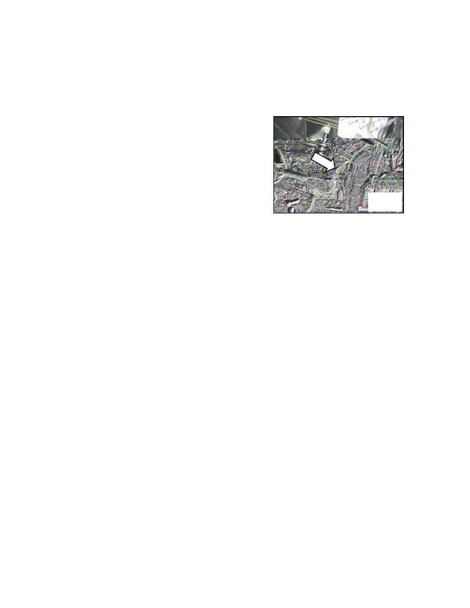
5. Reinstalling the ABS assembly 
Note: dismantle the hydraulic outlet 
plugs on ABS assembly only when the 
brake pipeline is to be fixed to avoid 
foreign matters entering into the braking 
system.  
Clean the electronic control module 
seals and BPMV sealing washer with 
alcohol.  
(1) Install the ABS assembly onto the 
bracket and screw it fast with a torque of 
18-30Nm.  
(2) Unfix the plugs on hydraulic outlets, 
fix brake pipes and make sure that they 
are correctly connected.  
(3) Fill new brake fluid into the liquid 
storage tank until the liquid reaches the 
MAX level and bleed as required.  
(4) Turn on the ignition switch and ABS 
alarm lamp must be on for 1.7 seconds 
before going off.  
(6) Clear the memory and check if there 
is any fault code.  
(7) Carry out final trial running to ensure 
that ABS is functioning well.  
 
Two. Description of ABS component 
functions 
1. Brake pressure modulator valve 
(BPMV) 
(1) Function: BPMV is installed in the 
engine room and will regulate the brake 
fluid applied onto each wheel during 
anti-lock braking. During normal 
braking, the BPMV maintains or reduces 
the pressure of brake fluid of each wheel 
regardless of the pressure of the brake 
cylinder.  
(2) Maintenance: BPMV is not a 
maintainable component and therefore 
not to be disassembled but replaced in 
the case of troubles. BPMV features four 
circuits which work on the front left, 
front right, rear left and rear right wheels 
respectively.  
(3) Composition of BPMV:  


40098


①Pump motor 
BPMV includes one motor-driven 
recycling pump which reduces the 
pressure and redirects the brake fluid 
from the brake caliper into the cylinder 
during anti-lock braking.  
②ABS valve 
The ABS valves reduce or maintain the 
brake fluid pressure of wheel circuits. 
They consist of four boost valves and 
four relief valves. During anti-lock 
braking, the electronic brake control 
module indicator valve reaches the 
correct position. With the anti-lock brake 
module, each hydraulic circuit pressure 
may be adjusted by the corresponding 
valves. Under normal circumstances, the 
boost valve is open and the relief valve 
is off so that the cylinder pressure may 
directly work on the brake during normal 

braking. Anti-lock brake valve is an 
inalienable part of the BPMV and can’t 
be repaired independently.  
2. Electronic brake control module 
(EBCM) 
(1) The major functions of EBCM are as 
follows:  
1) Monitor the input of wheel speed 
sensor 
2) Detect the skidding of wheels 
3) Control the braking system under the 
anti-lock or tractor control module.  
4) Supervising the system to ensure the 
normal electrical operation.  
The EBCM continuously checks the 
speed of each wheel to determine if the 
wheel has started to skid. If it is detected 
that the wheel has started to skid, the 
EBCM controls the valve status to 
regulate the brake fluid pressure of some 
or all circuits so that the car skidding 
may be prevented or the optimal braking 
or traction may be provided. The EBCM 
keeps on regulating the pressure of all 
hydraulic circuits until the car skidding 
is eliminated.  
The EBCM can also continuously 
monitor the status of ABS operation. In 
the case of any detected trouble, the 
EBCM can stop the ABS and turn on the 
ABS alarm lamp. The EBCM controls 
the display of ABS troubleshooting 
codes in the mode of troubleshooting.  
(2) Composition of EBCM 
1) Solenoid valve relay 
The solenoid valve relay provides power 
to the pump motor and the solenoid 
valve. The relay is normally on but 
turned off during startup. In other 
driving cycles, the relay will remain off 
so long as the troubleshooting code does 
not require that it be turned on. If the 
troubleshooting code is set to require 
that the relay be off, there will be no 
remaining battery voltage in the pump 
motor and the solenoid valve during the 

current driving cycle and subsequently 
the ABS will not work. The relay is an 
inalienable part of the EBCM and can 
not be independently repaired.  
2) Wheel speed sensor and gear ring 
Each wheel is equipped with one speed 
sensor which sends the wheel speed 
status signals to the EBCM with 
relatively small AC voltage. This voltage 
is created by the gear ring through the 
induction caused by the static sensor. 
The scale and frequency of the AC 
voltage are in direct proportion to the 
wheel speed. This signal is transmitted 
to the EBCM through the interfaces 
which may cause wrong codes or noise 
WSS. Two types of speed sensors are 
used in DBC7 system. 
3) Split-type wheel speed sensor and 
gear ring type  
The four wheel speed sensors are all 
installed in proximity to the gear rings. 
The sensors and the gear rings are 
independent devices and therefore can 
be independently repaired.  
(3) ABS alarm lamp (amber color) 
The ABS alarm lamp is located inside an 
instrument. In the case of ABS trouble 
detected by the EBCM, the alarm lamp 
will light up. The alarm lamp informs 
the driver of possible ABS troubles that 
cause the ABS to be disabled. If only the 
ABS alarm lamp is on, normal braking is 
still enabled. The ABS alarm lamp will 
be on in the following cases:  
1) ABS trouble: as said above, the ABS 
alarm lamp will light up if there is any 
ABS trouble detected.  
2) Checking of instrument bulb: during 
ignition, the ABS alarm lamp will also 
flash for about three seconds. The 
EBCM will instruct the ABS alarm lamp 
to flash for three seconds after it receives 
the ignition signal. 


(4) Braking alarm lamp (red)  
The braking alarm lamp in the 
instrument will turn on to warn the 
driver of any trouble in the braking 
system which may reduce the braking 
performance. This lamp will light up 
when the parking brake pedal is stepped 
down and not fully released. Or it will 
remain on if the brake fluid level switch 
is off (relatively low level in the brake 
fluid tank) until things have been 
corrected and improved. Some failure 
modes in the DBC7 system will also turn 
on this lamp to inform the driver that 
DDRP can’t be used any longer.  
Vent pipe 
EBCM’s C11 needle is a plastic vent 
pipe that directs the wind between 
EBCM and BPMV into the engine room.  
(5) Brake switch 
The brake switch inputs signals to the 
EBCM which informs whether the brake 
pedal has been stepped down with the 
input signals.  
3. Distribution of electronic braking 
power 
DDRP is a ratio system which maintains 
the car stability during braking. In the 
case of normal braking, it effectively 
balances the braking power to realize the 
same wheel speed. In the case of 
difficult braking, the car weight is 
mostly borne by the front wheels while 
the rear wheels will need relatively 
smaller braking power. DDRP utilizes 
the ABS rear boost valves and relief 
valves to maintain the braking pressure 
on the rear wheels to provide effective 
braking and car stability. In DDRP 
system, the rear pressure-keeping valve 
solenoid valve is powered by the ignition. 
In the case of the following troubles, the 
red braking alarm lamp will be turned on.   
(1) The two wheel speed sensors do not 
work on the same axle.  

(2) Rear boost solenoid valve does not 
work.  
(3) There is short circuit in the 
grounding circuit of battery 2 (motor 
input).  
(4) There is short circuit in the 
grounding circuit of battery 1 or open 
circuit (ECU input). 
(5) There is open circuit of motor 
grounding circuit and battery short 
circuit.  
(6) There is open circuit of ECU 
grounding circuit or battery short circuit. 
(7) There is open circuit of ignition 
circuit or short circuit in the grounding 
circuit.  


Section Three. Description of EBCM Wiring 
 
One. DBC7 (ABS/DDRP) ABS Wiring Diagram 
 

Wheel speed 
sensor 

Oil pump motor 

Parking brake

Brake fluid liquid 
level switch 

Braking alarm 
lamp 

ABS alarm lamp

Ignite

Ig

n

iti

o

n

 s

w

itc

h


To brake switch

B

ra

k

sw

itc

h


Power supply

40099


Content   ..  89  90  91  92   ..