Chery B11. Manual - part 54


  Index      Chery     Chery B11 - service repair manual


Search            


Content   ..  52  53  54  55   ..


Chery B11. Manual - part 54


Maintenance Manual for Chery·Oriental Son  

Engine Section


39


end 

of

valve rod

  valve seat 

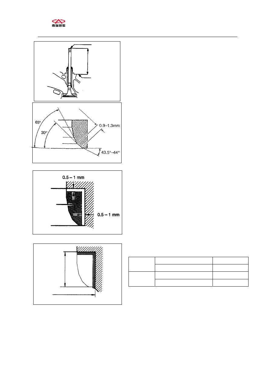
(1)Assemble the valve and measure the flange height of 

valve rod between the end of valve rod and seat 

surface of valve spring. If the measurement value 

exceeds the assigned limit value, the valve seat 

should be replaced. 

flange 

height 

of

l

d

seat  surface

of 

valve

i

Standard value: intake…………49.30mm 


               exhaust…………49.30mm 

Limit value: intake…………49.80mm 

             exhaust …………49.80mm 


  Points for maintaining the valve seat 

(1)  Before  maintaining  the  valve  seat,  check  the 

clearance between the valve duct and the valve rod. 

Maintain  after  replacement  of  valve  duct  if 

necessary. 


(2)  Repair the width and angle of the valve seat until 

their adjustment to the assigned value with abrasion 

machine. 

(3)  After repairing the valve seat, rub the valve and 

the valve seat in pairs with rubbing cream. Then 

check the flange height of valve rod. (Refer to the 

checking item of valve seat). 

  Points for changing valve seat  

(1)Cut a part of the to-be-replaced valve seat from the 

inner side to make it thinner and then remove it. 

(2)Repair and adjust the seat hole in cylinder cover 

according to the outer diameter of the enlarged 

valve seat. 

Diameter of valve seat washer 

enlargement size 0.30 

34.435-34.455 

intake 

valve seat

enlargement size 0.60 

34.735-34.755 

enlargement size 0.30 

31.935-31.955 

exhaust 

valve seat

enlargement size 0.60 

32.235-32.255 

(3)Before assemble the valve seat washer, heat 

the  cylinder  cover  to  the  temperature  of 

about 250℃, or cool the valve seat washer 

in the liquid nitrogen in order to engage 

inside the cylinder cover. 

(4)Repair  and  adjust  the  valve  seat  to  the 

assigned width and angle with a valve seat 

milling  cutter.  (Refer  to  Points  for 

maintaining the valve seat). 


cut 

height of valve 

seat washer 

enlarge  the

inner 

di

t


Maintenance Manual for Chery·Oriental Son  

Engine Section


40


Points for changing of valve duct 

(1) Press out the valve duct to the direction of 

cylinder with press machine. 

(2) Modify the valve duct hole of cylinder cover 

until the hole diameter gets to the size of 

enlarged valve duct to be installed. 

。Caution: 

flange 

value


Do not use a new valve duct with the same size 

as the disassembled valve duct. 

Duct hole diameter of valve in the cylinder 

cover. 

enlarge size 0.05:    11.05-11.068 

enlarge size 0.25:    11.25-11.268 

enlarge size 0.50:    11.50-11.518 

(3)As shown in the illustration, press the valve 

duct to the assigned flange value. 

Standard value: 14mm 

Caution: 

。Press the valve duct from the top surface 

of cylinder head. 

。the length of intake valve duct and exhaust 

valve duct are different. (Intake valve:

45.5,exhaust valve:50.5) 

(4)After installation of valve duct, insert the 

new valve and check if it could move smoothly.


Maintenance Manual for Chery·Oriental Son


Engine Section


Chapter 4 Crank Connecting Rod Mechanism 

1、

Piston and connecting rod component 


Daub  oil on all  the

inner parts when

installing.


Disassembling steps 


1. 

Connecting rod nut  2、Connecting rod cap    3、Connecting rod bearing

4、Piston and connecting rod component 

5、 Connecting rod bearing  6、No.1 compression ring  7、No.2 compression

ring  8、Oil control ring 

9、 Piston pin     10、Piston     11、Connecting rod     12、Connecting

rod bolt 


Maintenance Manual for Chery·Oriental Son


Engine Section


Disassembling Notice


Connecting Rod Cap 

Disassemble   

(1)  Mark cylinder number on the side of 

connecting rod big end to prepare for 

correct installation. 

cylinder 

number


(2) Take turns putting connecting rod, 

connecting rod cap and connecting rod 

bearing away, according to cylinder 

number. 


Piston Pin Disassemble 


(1) After inserting compression rod of the special tool 

from the top of piston marked with the arrowhead, 

install guide block C in the top of compression rod. 
(2)Keep forward mark of piston upward. Install piston 

and connecting rod component in base of piston pin 

installer (special tool).   


(3)Force piston pin out with pressure.   

Caution: 

Take turns putting piston, piston pin and 

connecting rod disassembled away according 

to cylinder number. 


piperA=17.9mm

piston pin

installer 

guide block B 

piperA=18.9mm

guide block C 

piperA=20.9mm

base 

piperA=21.9mm

compression 

rod


forward mark

forward mark


guide block C

base


Content   ..  52  53  54  55   ..