Chery A18. Manual - part 102
 

  Index      Chery     Chery A18 - service repair manual


Search            


Content   ..  100  101  102  103   ..


Chery A18. Manual - part 102


18 

4.11  (Another method of manual brake adjustment) 

Length  design  of  manual  brake  cable  of  the  vehicle  is 

fixed-length, it is possible to adjust effect  of  hand brake  by 

referring  to  disassembly  part  of  rear  brake,  and  achieve 

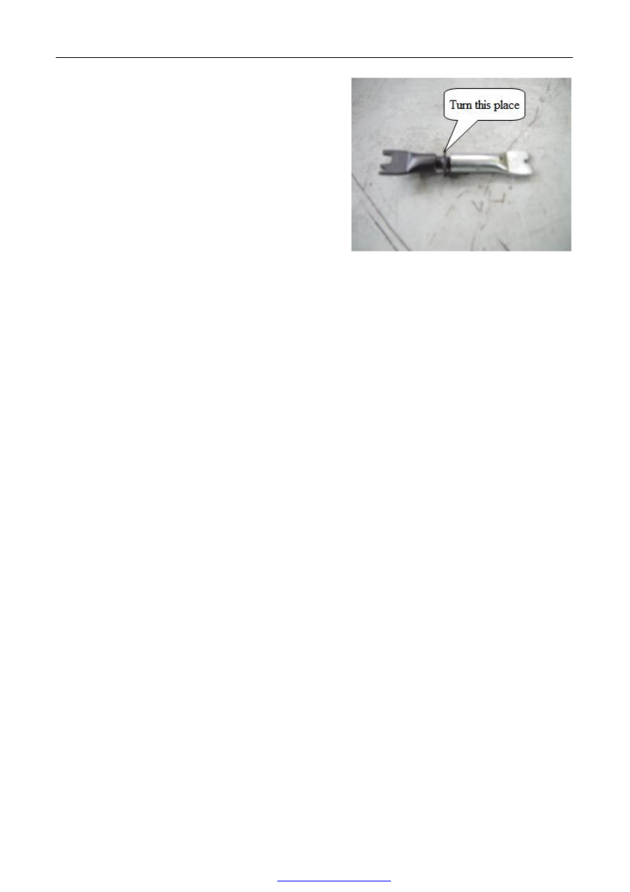
adjustment  of  manual  brake  by  adjusting  length  of  jogger 

(clockwise, loose; anticlockwise, tight). 


5.  Assembling step 


Conduct assembly in contrary step of disassembling step. 

Note: Please adjust parking brake after replaced shoe plate of brake or bracing wire of manual brake: 
²  Loosen parking brake handle 
²  Tread brake pedal once forcibly. 
²  Draw parking brake handle for four teeth. 
²  Fasten adjusting nut until these two wheels cannot be turned by hand. 
²  After completed abovementioned procedure, please loosen parking brake to check if two rear wheel can rotate 

freely, or repeat the above adjustment procedure. 


Section 5 


Addition of brake fluid and air exhaust 


1.  Tools requirement 


Diagnostic tools, 10# open end wrench. 


2.  General information 


In case that air enters into brake system while repairing or replacing brake parts, please conduct complete exhaust 

process. Before brake exhaust,  please  make cylinder  pistons front and rear exhaust return to  highest  position, and 

select using diagnostic tools to reset program in advance. In case diagnostic tools could not be used, please adopt 

the second kind of program and conduct operation according to described order strictly. 

In  case  that  air  enters  because  too  low  liquid  level  or  disconnection  of  brake  tube  of  primary  cylinder,  please 

exhaust  air  in  hydraulic  systems  of  the  four  brakes;  in  case  that  brake  tube  or  brake  hose  breaks  from  any 

connectors  between  primary  cylinder  and  brake,  it  is  necessary  to  exhaust  brake  system  relating  to  tube  or  hose 

only.   


19 

3.  Exhausting process of brake system 


3.1 

Exhausting step 

1) 

Lift and support vehicle properly. 

2) 

Assemble  exhaust  hose  of  transparent  plastic  on 

exhaust valve of brake tongs. 

3) 

Immerge  another  side  of  exhaust  hose  of  transparent 

plastic  to  cleaning  case  that  filled  some  clean  brake 

liquid. 

4) 

Tread  the  brake  pedal  for  five  to  six  times,  open 

exhaust valve to make brake fluid flow. 

5) 

Repeat the forth step all long until no bubble produces 

from brake fluid, and feeling of treading brake pedal is 

plenary, close exhaust valve. 

6) 

Disassemble exhaust hose made from transparent plastic from exhaust hose. 

Note: Above steps adapt to exhaust of brake pipelines of all brakes. 


3.2 

Exhausting step of brake system is: left rear→right front→right rear→left front, for vehicle has ABS system, 

please connect it to fault-diagnosing device and exhaust air from ABS system according to liquid adding and 

air exhausting process. 

3.3 

Conduct exhaust with brake loop 

Connect exhausting hose that has a container with exhausting valve of left rear brake tongs. Open exhausting valve, 

and tread brake pedal to bottom in five times at least. Brake liquid flew from exhausting valve should be clear and 

have  no  bubble,  hold  brake  pedal  at  position  of  bottom  and  close  exhausting  valve.  Release  brake  pedal,  and 

conduct same operation with brakes of other wheels. 


3.4 

Adding brake fluid 

For ensuring reliability  of running brake, do  not  forget to check  fluid level  of brake fluid  every  few time  or after 

exhaust of brake system, and add brake fluid in time if it is lacking. 


Note: 

(1)  Please  use  brake  liquid  that  assorts  with  standards  regulated  by  DOT  (use  DOT4)  only,  do  not  use  brake 

liquid mixed with other type. 

(2)  Brake fluid has strong water absorption, please put it in sealed container of original packaging. 

(3)  Brake  fluid  has  strong  corrosiveness,  if  spatters  it  on  skin  in  careless,  please  wipe  brake  fluid  on  skin  with 

water cloth and clean with soap and water. Brake fluid has strong corrosiveness to oil paint of vehicle body, 

do  not  spatter  brake  fluid  on  lacquer  finish  of  vehicle  body,  please  clean  it  with  water  immediately  after 

spatter it on. 

(4)  Observe fluid level of brake fluid in fluid reservoir during air exhaust, and add in time if it is lacking. 

(5)  Repeat  process  of  exhaust  for  several  times  during  manual  exhaust  until  air  in  brake  system  is  exhausted 

completely. 

(6)  Check if  leakage is existing with brake system after liquid adding and exhaust are completed, and  eliminate 


20 

Chapter 2    Disassembly, assembly, and overhaul of steering system 


I. 

Disassembly and assembly of steering engine 


1. 

System constitution diagram


1-Fluid reservoir of power assisted steering    2-Fixed bolt of plank 

3-Plank fixed nut                                              4-Oil outlet pipe 

5-Fixed plank of fluid reservoir                        6-Steering pump 

7-Tension gear                                                  8-Self-locking nut 

9-Adjusting nut                                                10-Slide rod 

11-Pipe clamp                                                  12-Steering engine 

13-Oil outlet pipe                                            14, 15-Fixed bolt 

16-Fixed nut                                                    17-Oil return pipe 


21 

2. 

Exploded view of steering gear assembly 


1-Sheath of tie rod    2-Power steering universal joint sheath    3-Nut    4-Nut-connecting rod 

5-Clip-sheath of tie rod and steering gear    6-Power steering gear with tie rod assembly 

7-Clamp ring-sheath and slide rod    8-Left steering tie rod assembly    9-Right steering tie rod assembly 

10-Left buttonhead latch assembly    11-Left steering tie rod assembly 

12-Universal  joint  sheath  of  power  steering    13-Steering  gear  assembly    14-Right  steering  tie  rod  assembly   

15-Right buttonhead latch assembly    16-Retaining clip    17-Rubber sheath 


2. 

Preparation 


Tools: 15#, 19# sleeve, 13#, 18# fixing wrench. 

Supplementary materials: Power steering fluid. 


3. 

Precautions 


3.1 

Please wear necessary appliances for labor protection to avoid of accident. 

3.2 

Avoid of contacting skin or eye with steering fat liquor while disassembling steering system. 


Content   ..  100  101  102  103   ..