Chery A15 / 480 LHD model. Manual - part 81
Pins:
1 sensor signal ground (ECU17#)
2 5V power (ECU32#)
3 sensor signal (ECU16#)
Troubleshooting: mainly check if there is short circuit
or open circuit on the connection between 3 lines on
sensor and ECU.
Check to see if there is short circuit, open circuit or
grounding between sensor wire harnesses.
※Coolant Temperature Sensor TF-W
Purpose: this sensor is designed to provide coolant
temperature information. To provide engine ECU with
water temperature signal used for control of ignition
timing and fuel injection pulse width in startup, idle
speed and normal operation.
Composition and principle: this sensor is a
thermistor of negative temperature coefficient (NTC)
with resistance value decreasing with the increasing of
coolant temperature except linear relation. The said
thermistor is installed in a heat-conducting sleeve.
ECU monitors water temperature variation by
converting resistance value of thermistor into a
changing voltage through a bleeder circuit (inner
structure of ECU).
Failure diagnosis: When coolant temperature is
higher than allowed upper limit or lower than lower
limit, failure mark of the knock sensor is set, engine
fault indicating lamp goes on and engine works in
failure mode. In this case ECU controls ignition and
fuel injection according to set water temperature for
failure mode, at the same time the fan is running at
high-speed mode.
Limiting data: 2.5±5%KΩ
Installation hint: tightening torque is 15Nm in
maximum.
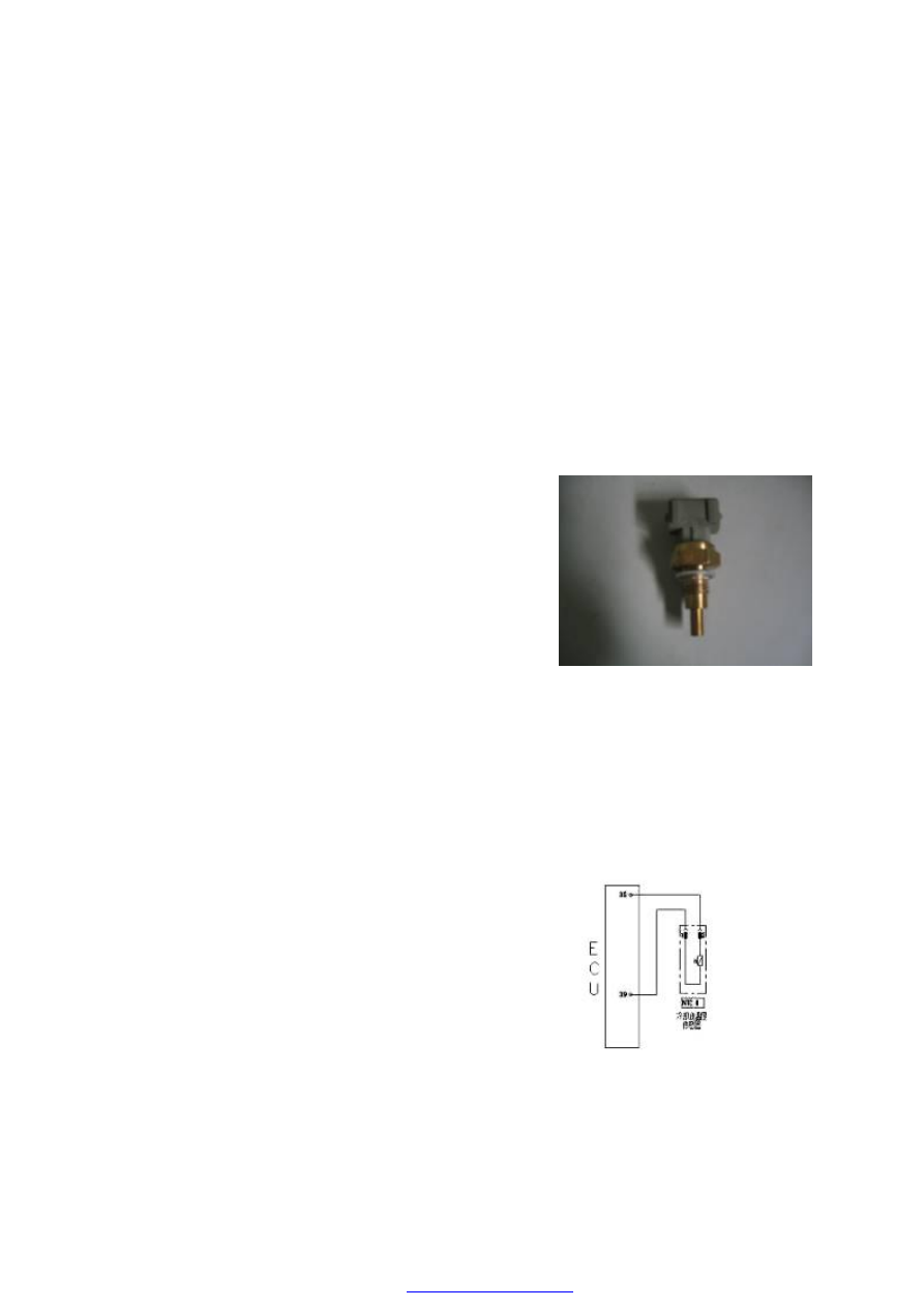
Coolant Temperature Sensor
Circuit diagram of Coolant
temperature sensor