Chery A15 / 480 LHD model. Manual - part 36


  Index      Chery     Chery A15 / 480 LHD model - service repair manual


Search            


Content   ..  34  35  36  37   ..


Chery A15 / 480 LHD model. Manual - part 36


REMOVAL/INSTALLATION OF AIRBAG SYSTEM 

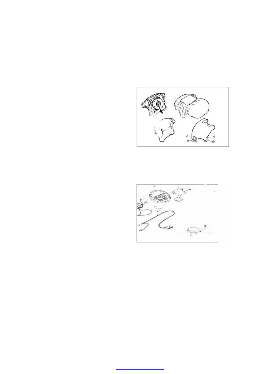
1. REMOVAL/INSTALLATION OF AIRBAG 

Removal: 

----Disconnect  the  negative  cable  of  the 

battery (—) 

Warning:  When  the  ignition  is  turned  off 

and  at  the  same  time  the  fuse  is 
taken  out,  the  airbag  control 
module  (BCM)  can  provide  the 
sufficient  voltage  for  1  minute  to 
activate the airbag. If the airbag is 
not  disconnected,  do  not  start  the 
maintenance work within 1 minute 
after  turning  off  the  power  supply 
to the BCM. If the airbag has been 
disconnected, 

the 

maintenance 

work 

can 

be 

carried 

out 

immediately  without  waiting  for 
the  discharging  of  1  minute.  The 
failure  of  shutting  off  the  SRS 
system  temporarily  during  the 
maintenance  work  will  result  in 
false  ignition,  physical  injury  and 
SRS system discarded.   


----Place the steering wheel at the center 

Warning:  When  dealing  with  the  airbag, 

please  face  the  front  side  of  the 
module  upwards  so  as  to  provide 
sufficient  spreading  space  in  case 
of false activation. The airbag may 
fly  to  the  people  or  objects 
resulting  in  injury  or  vehicle 
damage  due  to  the  lack  of 
spreading space.   

Remove  the  two  airbag  bolts  on  the  steering 
wheel. 

Pull out the horn and the airbag wiring harness 
plug from the airbag. Remove the airbag. 


Installation: 

----Connect wiring harness plug of the horn and airbag to the airbag socket. 

Install the airbag 

Install the airbag bolt 

Use a tightening torque of 13~17N.m to tighten the airbag bolt 

Connect it to the negative grid of the battery 

2. AIRBAG CONTROL MODULE (BCM) 

Warning:  Dealing  with  the  BCM  carefully  during  maintenance.  Do  not  knock  or  shake  the 
BCM.  Do  not  switch  on  the  SRS  circuit  before  installing  the  BCM  on  the  vehicle.  All  the 
BCM  bolts  must  be  tightened  carefully.  In order to  ensure  a  proper  functioning  of the SRS, 
the  arrow  on  the  BCM  must  point  at  the  direction  right  ahead  of  the  vehicle.  Though  the 
BCM  can  function  when  the  SRS  circuit  is  switched  on  before  installing  the  BCM  on  the 
vehicle, it may cause a potential false activation and consequential injury. 

Notes: If there is water entering  into the vehicle due to leakage, passing through deep water, 
flood  or  other  reasons,  the  BCM  and  BCM  connector  may  need  to  be  replaced.  Turn  the 
ignition switch to the “OFF” position; check the BCM area including the carpet etc. If there is 
any obvious dipping or dipped  mark, the leakage or dipped parts must be cleared, and at the 
same  time  replace  the  BCM  and  BCM  connector.  The  SRS  system  must  be  disconnected 
before  carrying  out  the  operations  above.  Please  refer  to  “Disconnection  of  the  airbag 
system” of this manual.   

Removal procedure 

Disconnect the SRS. Please refer to “Disconnection of the airbag system” of this manual. 

Remove the decoration panel on the left and right sides of instrument panel. 

Loosen the safety interlock of the BCM wiring harness connector. 

Remove the BCM wiring harness connector. 

Remove the BCM fastening bolts. 

Remove the BCM. 

Installation procedure 

Install the BCM according to the arrow on the BCM, which points at the direction right ahead 
of the vehicle. 

Install the BCM fastening bolts. 

Fasten the bolts with a torque of 8--12Nm. 

Connect the BCM wiring harness connector. 


Move the safety interlock head of the connector to “Lock” position. 

Install the decoration panel on the left and right of the instrument panel. 

Connect  the  SRS  system.  Please  refer  to  the  “Connection  of  the  airbag  system”  of  this 
manual. 

Warning:  All  the  BCM  bolts  must  be  tightened  carefully.  In  order  to  ensure  a  proper 
functioning of the SRS, the arrow on the BCM must point at the direction right ahead of the 
vehicle. Though the BCM can function when the SRS circuit is switched on before installing 
the BCM on the vehicle properly,  it  may cause a potential  false activation and consequential 
injury. 


3. WIRING AND CONNECTOR 

Note:  The  wirings  assembly  of  the  SRS 
protective  supplementary  system  and  that  of 
COWL  are  joined  together.  All  the  wirings  of 
this system are installed in a yellow corrugated 
conduit,  and  all  the  connectors  is  normal 
yellow. 

The  wiring  or the  wiring  connectors  are to be 
replaced under the following conditions: 

(a)  There  are  signs  of  damage  found  on  the 

wiring  or  wiring  connectors  of  the  SRS 
protective  supplementary  system  during 
troubleshooting. 

(b)  There  are  signs  of  damage  found  on  the 

wiring  or  wiring  connectors  of  the  SRS 
protective  supplementary  system  during 
inspection. 

Note:  If  there  is  any  damage  found  on  the 
wiring  of  the  SRS  protective  supplementary 
system,  the  whole  wiring  assembly  should  be 
replaced. 


4. SPIRAL CABLE   

The spiral cable (see the figure) is used for the 
circuit  linking  the  vehicle  body  and  the 
steering  wheel.  The  steering  wheel  must  be 
properly  installed  on  the  steering  column 
when the spiral cable  is  located in the middle, 
otherwise  the  spiral  cable  may  come  loose  or 
cause  other  malfunctions.  Please  refer  to  the 
instruction  for  proper  installation  of  steering 
wheel in this manual.   


5. STEERING WHEEL LINER 

----The SRS  airbag  is  installed  in the  steering 

wheel.  The  airbag  includes  the  activator, 
igniter  and  air  generator  etc.  When  the 
airbag  sensor  assembly  sends  out  the 


Content   ..  34  35  36  37   ..