Chery A15 / 480 LHD model. Manual - part 20


  Index      Chery     Chery A15 / 480 LHD model - service repair manual


Search            


Content   ..  18  19  20  21   ..


Chery A15 / 480 LHD model. Manual - part 20


REMOVAL AND INSTALLATION OF THE REAR SHOCK ABSORBER ASSY 


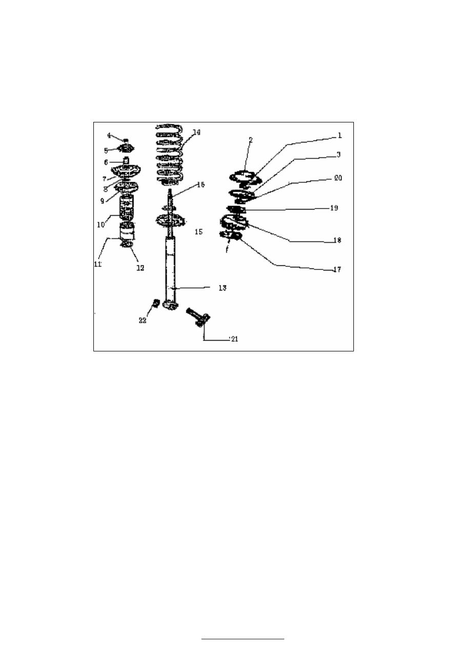
The structure of rear shock absorber assy is shown as the illustration: 


Illustration. Rear shock absorber assy 

1 Hexagon thin nut 15N·m              2 Rear strut upper cover            3 Belleville washer 

4 Hexagon thin nut 15N·m              5 Rubber bearing block II          6 Bearing sleeve 

7 Rear spring upper holder                8 Locating ring            9 Rear spring upper soft pad 

10 Rear bumper block      11 Dust cover      12 Valve cap      13 Rear shock absorber assy     

14  Rear  coil  spring        15  Rear  spring  bottom  tray          16  Bottom  tray  bearing  pad       

17 Bowl washer        18 Rubber bearing block I      19 Support disc    20 Hexagon thin nut 

25N·m            21 Bolt            22 Nut 70 N·m 


Precaution:  Before  the  procedure  below,  the 
careless  pull  may  lead  the  disconnection  of 
the  harness  if  the  ABS  vehicle  speed  sensor 
is  not  removed  first.  Therefore,  before  the 
following  procedure,  remove  the  ABS 
vehicle  speed  sensor (the  axle  side) first and 
fix it in a proper position in order to keep the 
sensor 

untouched 

during 

the 

vehicle 

maintaining. 

Assemblage  of  the  rear  shock  absorber 
(refer  to  the  illustration  of  the  rear  shock 
absorber assy) 

----Cover the rear spring bottom tray 15 onto 

the rear shock absorber assy 13, fix it on 
the rear shock absorber with the pressure 
of  9.5~10kN,  and  then  set  the  bottom 
tray  bearing  pad  with  the  pressure  of 
2~3kN. 

----Cover the rear coil spring 14 and the valve 

cap  12  onto  the  piston  rod  of  the  rear 
shock  absorber  in  sequence,  and  then  set 
into the rear bumper block 10 and the dust 
cover  11  which  have  been  assembled 
together; 

----Press  the  rear  coil  spring  14  to 

280~300mm,  and  then  fix  the  locating 
ring  8,  the  rear  spring  upper  soft  pad  9, 
the  rear  spring  upper  holder  7,  the 
bearing  sleeve  6,  and  the  rubber  bearing 
block II 5. Tighten the hexagon thin nut 4 
to the specified torque (15N·m); 


Installation position of the spring holder 

Installation of the shock absorber spring 

----As the illustration shows, aperture a must 

aim  at  the  bush  of  the  connecting  sleeve 
2 when install the rear spring bottom tray, 
otherwise  the  spring  tray  1  would  hit  the 
tire under extreme steering condition. 

----As  the  illustration  shows,  please  pay 

attention  to  the  installation  position  of 
the rear spring upper soft pad. 

Installation  of  the  rear  shock  absorber 
assy  (refer  to  the  illustration  of  the  rear 
shock absorber assy) 


Installation position of the spring bottom 

tray 

----Install upward the rear shock absorber assy 

from  the  vehicle  body  bottom  and  extend 
the piston rod into the carriage through the 
rear shock absorber holder; 

----Inside the carriage, cover bowl washer 17, 

rubber  bearing  block  18  and  support  disc 
19  onto  the  piston  rod  in  sequence,  and 
then  tighten  the  hexagon  nut  20  with 
tightening  torque  of  20N·m.  (shown  as 
the assy picture above) 


----Lift  the  vehicle,  and  then  put  the 

connecting  sleeve  of  the  rear  shock 
absorber 

into 

the 

corresponding 

installation position on the rear axle assy 
and  then  tighten  the  bolt  21  and  the  nut 
22 with the specified torque (70±7N·m) 

----Fix  the  tire,  ground  the  vehicle  and 

tighten  the  hexagon  thin  nut  20  with  the 
specified torque (25 N·m) 

----Fix the belleville washer 3 and tighten the 

hexagon  thin  nut  1  with  the  specified 
torque (15 N·m) 


----Fix the rear shock absorber upper cover 2, 

in  order  to  keep  away  from  the  dust  and 
dirt which could lead to abnormal wear on 
the piston rod. (shown as the picture) 


OVERHAUL OF THE FRONT AND REAR AXLE 


Trouble 

Causes 

Solutions 

Deflecting of 

vehicle running 

1.  Different  tire  pressure  of  both 

sides 

2.  Half  way  releasing  of  front 

braker 

3.  Invalidation  of  front  spring  or 

housing 

4.  Inaccurate  alignment  of  front 

wheel 

5.  Invalidation of shock absorber 
6.  Invalidation  of  metal  rubber 

bushes of suspension 

7.  Deformation  of  vehicle  chassis, 

frame or control arm 

1.  Adjust 
2.  Overhaul, adjust 
3.  Replace 
4.  Check, adjust 
5.  Replace 
6.  Check  and  replace  the 

damaged bushes 

7.  Replace or align 

Abnormal wear 

on tire 

1.  Inaccurate alignment of wheel 
2.  Serious  wear  or  loose  of  metal 

bushes of suspension system 

3.  Looseness  of  steering  link  ball 

joint 

4.  Looseness 

of 

front 

wheel 

bearing 

1.  Check, adjust 
2.  Replace 
3.  Replace 
4.  Replace 

Oscillation of 

vehicle 

1.  Low or different tire pressure 
2.  Inaccurate  alignment  of  front 

wheel 

3.  Invalidation of stabilizer bar 
4.  Unbalance of wheels 
5.  Looseness of hub bearing 
6.  Improper adjustment of steering 

gear 

or 

serious 

wear 

of 

components 

1.  Adjust tire pressure 
2.  Check, adjust 
3.  Replace 
4.  Balance 
5.  Adjust 
6.  Adjust 

Abnormal noise 

of chassis 

1.  Too  small  tightening  torque  of 

chassis sub-frame bolt 

2.  Looseness of rear axle bracket 
3.  Abnormal  noise  of  front  and 

rear shock absorber 

4.  Looseness  of  rear  axle  rubber 

hinge bolt looses 

1.  Tighten  according  to the 

specified torque 

2.  Tighten 
3.  Check, replace 
4.  Check, tighten 


Content   ..  18  19  20  21   ..