Chery A15. Manual - part 279
 

  Index      Chery     Chery A15 - service repair manual


Search            


Content   ..  277  278  279  280   ..


Chery A15. Manual - part 279


(IV) Assembling the master pump 

1. Apply both sides of the piston cup 
with lithium-soap glycol grease. 
2. Insert the piston into the master pump.  
3. Fix the push rod assembly with the 
spring snap ring. 
(V) Fixing master pump 
1. Fix the master pump. 
Insert the quick coupler of the clutch 
master pump into the clutch pedal and 
screw tight the set nut. Torque: 7.8 N.m. 
Fasten two nuts (M=11+1Nm) onto the 
two welded bolts on the vacuum booster 
bracket and fasten the clutch master 
pump onto the vacuum booster bracket;  
2. Connect the pipeline. 
3. Bleed the air in the hydraulic system 
and adjust the clutch pedal height.  
II. Clutch sub-pump 
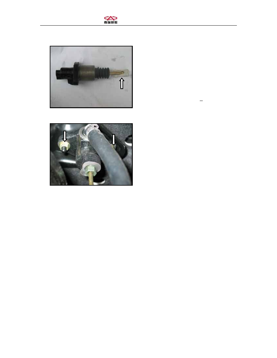
(I) Unfixing sub-pump 
1. Unfix the hydraulic pipeline of the 
sub-pump 
2. Release the two set bolts for the sub-
pump and the gearbox and then 
dismantle the sub-pump.  
 
 
(II) Disassembling sub-pump 
1. Pull out the dust cover and push rod 
2. Dismantle the piston with a caliper 
and then blow the piston and the spring 
out of the sub-pump with compressed air.  
 
 
Note: use cotton cloth to hold the sub-
pump piston and spring during 
blowing to avoid personal injury by 
the flying piston.  


(III) Checking sub-pump 

Clean the disassembled parts with 
compressed air.  
1. Check if there is any scratch or rust on 
the sub-pump and clean or replace the 
sub-pump if any.  
2. Check if the piston and piston cup 
suffers any abrasion, scratch, crack or 
burr.  
3. Check if the push rod suffers any 
abrasion or damage.  
(IV) Assembling sub-pump 
1. Apply the piston with lithium-soap 
glycol yellow oil.  
2. Fix the piston and the spring into the 
sub-pump; 
3. Fix the dust cover and the push rod 
onto the sub-pump  
(V) Fixing sub-pump 
1. Fasten two set bolts (M=11+1Nm) of 
the sub-pump and gearbox.  
2. Connect the hydraulic pipeline 
between the master pump and the sub-
pump.  
3. Add brake fluid and then bleed the air 
in the clutch hydraulic pipeline.  
4. Check if the hydraulic system suffers 
any leakage.  


Section Six: Disassembly and Repair of Clutch Parts 
 
 
I. Disassembling the clutch 
1. Mark accordingly on the flywheel and 
clutch cover 
2. Fasten the flywheel with a special tool 
and release the set bolts of the clutch and 
the flywheel in diagonal sequence one 
round each time until the spring tension 
is eliminated. 
 
3. Screw off the set bolts of the clutch 
pressure plate assembly and then take off 
the clutch pressure plate assembly and 
the wearing plate.  


4. Dismantle the release bearing and 
release fork from the transmission axle. 


1. Clutch pressure plate assembly 

2. Bolt 

3. Special tool (flywheel bracket) 


II. Checking the clutch 
(I) Checking wearing plate 
1. Check if the release bearing rotates 
flexibly.  
2. In the case of locked or inflexible 
release bearing, please replace the 
bearing.  
3. Clutch wearing plate assembly: 
measure the pitch between rivet head 
and the wearing plate surface. Replace 
the wearing plate assembly when the 
pitch in any screw hole has reached the 
limit.  


Standard value 

Maintenance 

Rivet head set-in 

pitch 

1.5mm 
0.06in 

0.5mm 
0.02in 


(II) Clutch pressure plate assembly 
1. Check if the diaphragm spring suffers 
any abnormal abrasion or damage.  

2. Check if the pressure plate suffers any 
abrasion or overheated spot.  
3. In the case of anything abnormal, 
replace the pressure plate assembly. Do 


Content   ..  277  278  279  280   ..