Chery A15. Manual - part 278
 

  Index      Chery     Chery A15 - service repair manual


Search            


Content   ..  276  277  278  279   ..


Chery A15. Manual - part 278


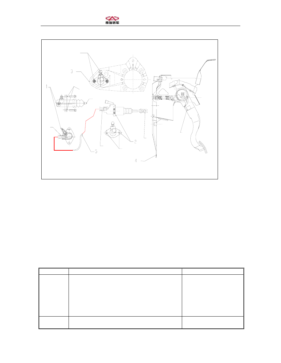
1. Clutch sub-pump; 2. Clutch main cylinder; 3. Vacuum booster bracket 
4. Clutch pedal assembly; 5. Outlet pipeline assembly 


Section Two: Troubleshooting 


Symptom Cause 

Solution 

Skidding 
clutch 

Wrong clutch pedal free stroke (clearance) 
Worn-out or polluted clutch wearing plates 
Deformed wearing plates, pressure plate or 
flywheel 
 
Weakened diaphragm spring 

Adjust free stroke 
Replace wearing plate 
Replace wearing plate, 
pressure plate or 
flywheel 
Replace clutch pressure 
plate assembly 

Clutch not 
fully 

Wrong clutch pedal free stroke 
Weakened diaphragm spring or worn-out 

Adjust free stroke 
Replace  pressure  plate 

disengaged  tapered head.  

Rusted input shaft spline 
Damaged or worn-out gearbox input shaft spline
Clutch wearing plate assembly vibrates too 
much 
Damaged or polluted clutch wearing plate 
 
Air in the hydraulic system 
Leakage in the hydraulic system 

assembly 
Lubricate 
Replace input shaft  
Replace wearing plate 
assembly 
Replace wearing plate 
assembly 
Bleed the air 
Check and repair the 
leakage 

Vibrating 
clutch 

Worn-out of clutch wearing plate (like glass) 
 
Polluted clutch wearing plate 
Release bearing has difficulty sliding on the 
gearbox bearing sleeve 
Vibrating clutch wearing plate assembly or bad 
contact of wearing plate 
Weakened damping spring of clutch wearing 
plate assembly 
Clutch wearing plate rivet loosened 
 
Deformed pressure plate or flywheel 
 
Damaged engine fixing pad or loosened set bolt 
or nut. 

Repair or replace 
wearing plate 
Replace wearing plate 
Lubricate 
 
Replace wearing plate 
assembly 
Replace wearing plate 
assembly 
Replace wearing plate 
assembly 
Replace pressure plate 
assembly or flywheel 
Screw tight or replace 
fixing pad 

Noisy 
clutch 

Worn-out or damaged release bearing 
Worn-out input shaft front bearing 
 
Abnormal noise of clutch wearing plate 
 
Cracked clutch wearing plate 
 
Abnormal noise of pressure plate and diaphragm 
spring 

Replace release bearing 
Replace input shaft 
bearing 
Replace wearing plate 
assembly 
Replace wearing plate 
assembly 
Replace pressure plate 
assembly 

Clutch 
can’t be 
disengaged 

Polluted clutch wearing plate 
 
Severe abrasion of clutch wearing plate 
 
Exposed rivet 
 
Weakened torsion spring 
 
Leakage in the hydraulic system 
 
Air in the hydraulic system 

Replace wearing plate 
assembly 
Replace wearing plate 
assembly 
Replace wearing plate 
assembly 
Replace wearing plate 
assembly 
Check and repair leakage
Bleed the air 
Bleed the air 


Section Three: Bleeding Clutch System 
 
When the clutch is being repaired or it is 
suspected that there is air in the clutch 
pipeline, it becomes necessary to bleed 
the air in the clutch assembly. 
Note: wash away any brake fluid on 
painted surfaces.  
1. Add brake fluid into the fluid tank of 
clutch. Frequently check the brake fluid 
level in the fluid tank and add if 
necessary.  
2. Connect one plastic tube to one 
bleeding bolt (as the figure shows) and 
insert the other end of the tube into the 
brake fluid container that is half

 topped

.  

3. Bleed the air in the clutch pipeline.  
(a) Slowly step down the clutch pedal;  
(b) Do not release while stepping down 
the clutch pedal, release the bleeding 
bolt of the clutch sub-pump until the 

fluid starts to outflow and then fasten the 
bleeding bolt.  
(c) Repeat the above procedure until 
there is no air bubble in the fluid.  


Section Four: Clutch Pedal 
 
I. Checking and adjusting clutch pedal 
1. Check the height of pedal. 
Height of pedal from carpet: 160-180mm (6.33-7.10inch). Adjust the pedal height 
adjusting nut and rotate the set bolt until the proper height is achieved and then fasten the 
nut.  
2. Check the pedal free stroke and push rod clearance.  
Pedal free stroke 
Push the pedal outward until the resistance is felt from the clutch. Free stroke: 5-15mm 
(0.197-0.591inch). 
Push rod clearance 
Push the pedal slightly with one finger until the resistance increases a little. Push rod 
clearance on top of pedal: 1-5mm (0.039-0.197inch).  
3. Adjust pedal free stroke and push rod clearance if necessary.  
(a) Release the set nut and turn the push rod until the free stroke and clearance are proper.  
(b) Fasten the set nut.  
(c) Adjust the pedal free stroke and check pedal height.  
4. Check clutch disengagement location. 
(a) Pull the parking brake handle and place the wheel wedge. 
(b) Start the engine for idle running. 
(c) Do not step down the clutch pedal and slowly push the gear lever to reverse position 
until gear engagement.  

(d) Slowly step down the clutch pedal and measure the stroke from the disappearance of 
gear noise (disengagement location) to the stroke terminal.  
Standard stroke: 25mm (0.98inch) or above (from pedal stroke terminal to the 
disengagement location). 
If the stroke does not comply with requirements, please check the following:  

•  Check the pedal height 

•  Check the push rod clearance and pedal free stroke 
•  Bleed the air in the clutch pipeline 

•  Check the clutch over and disc. 


Section Five: Hydraulic Control System 
 
 
I. Clutch master pump 
(I) Unfixing the master pump 
1. Suck out the brake fluid with a sucker.  
2. Detach the clutch pipeline. 
3. Detach the clutch master pump push 
rod from the clutch pedal.  


4. Screw off the set nut, detach the 
clutch pedal from the master pump and 
pull out the master pump.  


(II) Disassembling master pump 
1. Dismantle the pipeline 
2. Dismantle the push rod, pull back the 
protective hood and unfix the spring 
snap ring with a spring caliper.  
3. Dismantle the piston.  
(III) Checking master pump 
Clean the disassembled parts with 
compressed air.  
1. Check if there is any scratch or rust on 
the master pump and clean or replace the 
master pump if any.  
2. Check if the piston and piston cup 
suffers any abrasion, scratch, crack or 
burr.  
3. Check if the push rod suffers any 
abrasion or damage.  


Content   ..  276  277  278  279   ..