Chery A15. Manual - part 269
Eighteen. Troubleshooting code – engine fault indicator light
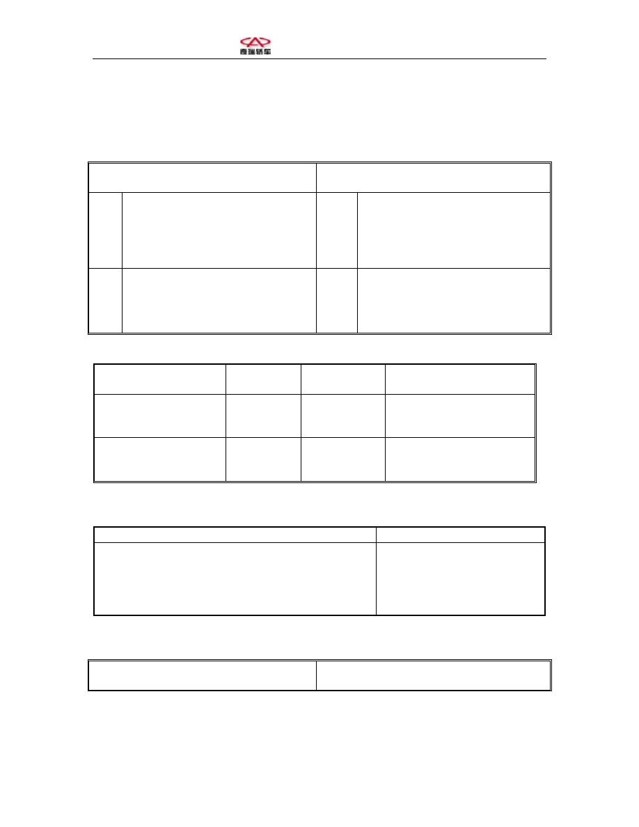
1. Troubleshooting code setup conditions and emergency scheme
P0650 Short circuit between fault indicator
light and power source anode
P0650 Open circuit of fault indicator light
or its ground fault
Ju
dg
m
en
t
co
nd
iti
on
s
• Duration > 2s
Ju
dg
m
en
t
co
nd
iti
on
s
• Duration > 2s
E
m
er
ge
nc
y
sc
he
m
e
• Off
E
m
er
ge
nc
y
sc
he
m
e
• Off (open circuit)
• Normally on (ground fault)
2. Relevant computer terminals and measurement
Wiring terminal
ECM
System fault
indicator light
Normal measurement signal
Ignition switch
\
See electrical
system
description
12V
Indicator light drive
48
See electrical
system
description
Off = 12V, On = 0V
3. Troubleshooting procedure
Possible cause
Reference maintenance scheme
1) Defected fixing of fault indicator light bulb
2) Fault of circuit to the ignition switch
3) Short circuit between the drive circuit and the power
source cathode
4) Fault indicator light bulb is damaged
1) Fix the bulb again
2) Repair the wire harness
3) Repair the wire harness
4) Replace the light bulb
Nineteen. Troubleshooting code – power source control
1. Troubleshooting code setup conditions and emergency scheme
P1230 Short circuit between master relay
and power source anode
P1230 Open circuit of master relay or its
ground fault