Chery A15. Manual - part 260


  Index      Chery     Chery A15 - service repair manual


Search            


Content   ..  258  259  260  261   ..


Chery A15. Manual - part 260


Section Six. Exhaust Emission Control Component 


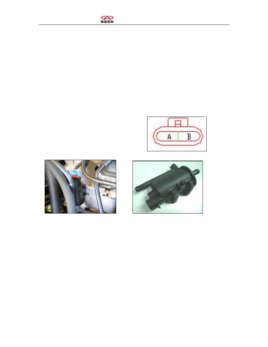
One. Charcoal canister cleaning solenoid valve (ECP) 
1. Functions and principles 
The ECM controls the gasoline flow into the intake manifold by the cleaning solenoid 
valve; for the ECM’s output pulse square wave, gasoline steam flow and the duty ratio of 
the control pulse square wave are linear to each other.  
The ECM will change the cleaning timing and speed of the charcoal canister as per the 
engine speed and load.  
Wiring terminal: A-ECM, B- +12V; 
Fixing: in the front right position of the engine and between the fuel steam charcoal 
canister and intake manifold.  
2. Component parameter:  
Working voltage: 8~16 V 
Ultimate voltage: 25 V (<60 S’) 
Working temperature: -40~120℃ 
Impedance: 19~22 

Ω 

Inductance: 12~15 mH 


3. Fault diagnosis 
Tips
: All the following judgments are based on the normal operation of the vehicle, wire 
harness and other system components. 
The faults are discovered by the system and displayed on the diagnostic instrument; self 
damage, blocked charcoal canister and wrong fixing of pipes.  


Two. Three-way catalyst 
1. Functions and principles 
The function of the three-way catalyst is to turn 
the harmful exhaust produced by the engine into 
harmless exhaust for emission into the air.  
The internal structure of the three-way catalyst features 
honeycomb pipelines on whose walls are coatings of 
such rare metals as platinum, rhodium and palladium as 
the catalyst.  
The power loss of the three-way catalyst is about 3-4%.  
Fixing: the three-way catalyst is connected in series 
between the air exhaust manifold and the muffler and 
located behind the oxygen sensor.  
The catalyst in the three-way catalyst can work 
to promote the oxidization between HC and CO 
and turn them into H

2

O and CO

2

 respectively; 

meanwhile, it turns the NO

x

 into N

2

.  

Functions of the three-way catalyst:  
HC, CO and NO

x


→three-way catalyst→ H

2

O, 

CO

2

 and N

2


Oxidization:  

CO + 1/2 O

2


→ CO

2


HC + O

2


→ H

2

O + CO

2


Deoxidization:  

NO + CO 

→ 1/2 N

2

 + CO

2


HC + NO 

→ N

2

 + H

2

O + CO

2


The catalyst’s is most effective to promote the 
oxidization between HC and CO when the AFR 
is higher than 14.5 while it is most effective to 
promote the deoxidization of NOx when the 
AFR is lower than 14.8. In consideration of both, 
the overall transfer efficacy of the three-way 
catalyst shall be between the AFR of 14.6-14.7.  
The ECM controls the AFR to be above the 
optimal AFR for the three-way catalyst by the 
signals from the oxygen sensor.  


2. Component parameter 
Optimal working temperature: 375~800℃ 
(Instantaneous temperature endurance: 950℃) 
Optimal working AFR: 14.6-14.7 
3. Fault diagnosis 
Tips
: All the following judgments are based on the normal operation of the vehicle, wire 
harness and other system components. 
Failure due to intoxication with heavy metals (like lead and manganese), phosphor or 
sulfur;  
Failure due to high temperature burning (e.g. single engine cylinder burning); 
Broken carrier due to external impact or sudden freezing; 
Blocked by foreign matters (e.g. engine oil burning) 


Chapter Five Engine Troubleshooting 


Section One. Reading and Elimination of Engine Troubleshooting Code 

 
1. Reading of troubleshooting code of engine 
In the case of system or component troubles when the engine is running, the engine fault 
indicator light will be automatically turned on to inform the driver to check and repair in 
time.  
 
1: Engine fault indicator light diagnosis 
4, 5: Grounding 
7: Engine, ABS data output 
9: SRS diagnosis 
16: Power source 
 
 
The diagnostic seat is located under the instrument and on the right to the central junction 
box.  
In the case of emergency fault diagnosis, the fault indicator lights may also, via special 
operation, be made flashing to read engine troubleshooting code, which is the most 
economic way to obtain the troubleshooting codes.  
The operating procedure is as follows:  
(1) Check and make sure that the storage battery shall be able to accommodate the 
engine’s startup turning speed; the engine and vehicle components are shut off; the 
throttle is fully closed and the gearbox is at neutral gear;  
(2) Turn off the ignition switch; 
(3) Connect Troubleshooting Terminal 1 to Ground Terminals 4 and 5; 
(4) Turn on the ignition switch but do not start the engine;  
(5) If the system suffers any fault or the fault code is not reset after the fault is eliminated, 
the engine fault indicator light will keep flashing and output the code of faults detected 
by the system (the idle speed control valve will reset while the troubleshooting code is 
being read); 
(6) Shut off the ignition switch and disconnect the troubleshooting circuit after the 
troubleshooting code has been read.  
The rules for the flashing of fault indicator lights are as follows:  
Report the faults as per the sequence of faults detected;  


Content   ..  258  259  260  261   ..