Chery A15. Manual - part 213


  Index      Chery     Chery A15 - service repair manual


Search            


Content   ..  211  212  213  214   ..


Chery A15. Manual - part 213


(3). Fix parking brake dragline on parking brake arm drag, and assemble brake shoe 

onto brake cylinder wheel. 

(4). Fix lower retracing spring, and regulate wedge spring and retracing spring. 

(5). Assemble brake drum and rear wheel hub bearing. 

(6) Fully operate brake pedal for several times to set brake shoes in normal working 

position 

(II). Replacing Brake Strip 

Check brake strip for oil stains, and sand with a piece of sandcloth if any. In case 

brake strip is worn to the limit, it shall be replaced together with brake shoes. 

Note: When replacing brake strip, new brake strip of the same quality made by 

the same manufacturer shall be used. 

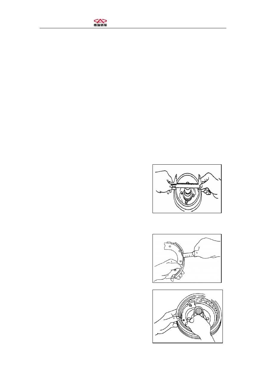
(III). Checking Rear Drum Brake 

(1). Measure brake drum inner diameter as shown 

in the figure. 

Standard inner diameter: 200mm 

Service limit: 201mm 

In case scratches or slots occur on brake drum inner   

diameter after use, reprocess it on a lathe. 

Note: Do not exceed service limit when reprocessing with a lathe. 

(2). Measure brake strip thickness as shown in 

the figure. 


Note: Service limit: 2mm 


(3). Check the contact between brake strip and   

brake drum as shown in the figure. 


(IV). Maintenance of Brake Wheel Cylinder 

(1). Check brake wheel for oil leakage and dust cover for cracks. 

(2). Disassemble brake wheel cylinder and check for scratched piston and cylinder 

wall, broken spring and damaged oil seal, and replace the wheel cylinder if any of the 

above is found. 

(V). Maintenance of Spring 

Check spring for breaking, deformation or weakening, and replace it if any. 


III. Regulation of Parking Brake 

Rear drum brake clearance is self-regulated, therefore no need to regulate parking 

brake except when replacing parking brake dragline, brake shoe assembly or brake 

wheel cylinder. Regulating steps: 

(1). Release parking brake handle. 

(2). Fully operate brake pedal for one time. 

(3). Lift parking brake handle up to the fourth   

ratchet. 

(4). Tighten regulating nuts as shown in the figure   

until the two wheels are not rolled by hand.             


(5). Release parking brake and check if rear wheels are rolling smoothly. 


IV. Brake Pedal 

(1). Adjustment of Clearance between Brake Pedal and Floor 

(1). Operate brake pedal 7 with a 300N force as shown in the figure. The clearance 

between brake pedal 7 and floor 8 shall not be less than 80mm. 

Regulating nut 

Regulating nut 


1. Nut   2. Brake master cylinder   3. Vacuum tube check valve   4. Vacuum booster 
5. Push rod fork   6. Locknut   7. Brake pedal   8. Floor   9. Spring locking piece   10. Pin 
11. Push rod 

(2). If the clearance is less than the limit value, first unfix spring locking piece 9 that 

connects vacuum booster 4 and brake pedal 7, then pull out pin 10, loosen locknut 6 

and adjust push rod fork 5 until the requirement is met. 

(II). Adjustment of Brake Pedal Free Travel 

(1) Shut off engine and operate brake pedal for several times to eliminate the vacuum 

left in vacuum booster. 

(2). Press down brake pedal with hand until resistance is felt, the pressed distance is 

the free travel. Required value for free travel is 3-6mm

(3). In case of incompliant free travel, adjust the clearance between vacuum booster 

push rod and brake master cylinder. 

Note: Free travel of brake pedal shall not be shortened by carpet laid on floor, 

for critical shortage of free travel may disable the brake. 

(III). Maintenance of Brake Pedal 

Check brake pedal for smooth operation, and demount if for inspection should 

abnormity be found. Check brake pedal for distortion and deformation, and replace it 

if any. Check brake pedal shaft for wear or deformation, and replace it if any. All shaft 

pins shall be lubricated when assembling. 


V. Inspection of Vacuum Booster 

(I). Checking Boosting Performance 

In case of failed vacuum booster, driver may feel a notable increase in resistance 

when operating brake pedal, and the booster assembly shall be replaced. Following 

shortcuts may also been used to make judgment on vacuum booster condition. 

(1). Shut off engine and operate brake pedal for several times to eliminate the vacuum 

left in vacuum booster. 

(2). Press down the brake pedal with a moderate force, and maintain the pedal at a 

certain position. 


(3). Start engine, and if an obvious automatic sinking (boosting effect) is felt, the 

vacuum booster is in good condition; and if nothing happens to brake pedal, the 

vacuum booster is out of service and shall be replaced. 

(4). Replace the sealing plate together with the booster assembly. Tightening torque of 

booster assembly and brake master cylinder set bolts is 20Nm. 

(II). Checking Vacuum Tube Check Valve of Booster 

If the check valve installed in vacuum tube is failed, the driver will feel great 

resistance when operating brake pedal, and braking performance will obviously 

decline. 

Blow compressed air into check valve, the air shall be able to pass the valve in the 

direction of arrow marked on valve body and not able to pass in the reserve direction. 

Blowing air through the valve by mouth to check the unidirectional passing capability 

will also work. The vacuum tube assembly shall be replaced in case of bad check 

valve sealing. 


Content   ..  211  212  213  214   ..