Chery A15. Manual - part 192


  Index      Chery     Chery A15 - service repair manual


Search            


Content   ..  190  191  192  193   ..


Chery A15. Manual - part 192


  Chery A15 Maintenance Manual 


Degassing of the gas spring   

Fix the gas spring onto pliers and cut off 

1/3 of total length of the gas spring, with 

the total length being measured from the 

edges of piston rod. During cutting 

process, the operator should wear goggles. 

It is suggested to cover cutting area with 

cloth so that there won’t be any oil 

splashes. 


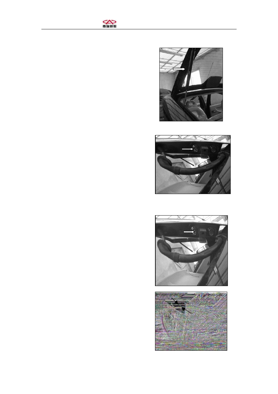
4.  Another operator pulls out the bolts and 

removes the rear door. When putting the 

door on a flat surface, apply a suitable 

protective layer between the contacting part 

of the surface and the rear door. If the rear 

door is to be replaced, remove the rear 

window before removing the set bolts for 

the door. Installing procedures are in the 

reversed order.   Coating techniques have 

been stated in “Coating procedures for steel 

sheet”. 


5. Any necessary adjustment of rear door edges 

may be performed through the hinge and the 

slot on the trough hole of the hinge is 

intended for this purpose.   


6. If any transverse adjustment of the rear door 

is necessary, move the hinge on the side. 

Measure the distance after moving it several 

times. Keep on moving it until it reaches the 

set value of the regulator. The adjustment 

may also be realized by moving the top 

center. 


  Chery A15 Maintenance Manual 


After adjustment is completed, check if the rear 

door is aligned with its adjacent surface. Check 

if sealing adhesive tapes are well bound and, if 

so, it is possible to equip water sealing on the 

rear door, which can prevent water, air and dust 

from entering or sending clicking sounds.   

Check if the transparent plastic adhesive tape 

between the rubber block and vehicle body 

paint coating still exists. In case that there 

exists no adhesive tape or it has been aged, 

clean contacting surface with isopropyl alcohol 

or heptane and reaffix the adhesive tape. 


Removing the slamming board   

Remove the two (2) set screws for each of the 

two slamming boards, which are on the side of 

the luggage compartment. 


Remove upper part of the center lock body 

Remove two set screws between the door 

opening and remove the upper part of the center 

lock body. 


Remove two set bolts between lower part of the 

center lock body and the rear boarding. As to 

A15 vehicle with decorative board for luggage 

compartment, remove the decorative board 

first, then the set bolts may be accessed. 


  Chery A15 Maintenance Manual 


Installing procedures for the lock are in the 

reversed order. Tightening torque for set screws 

on lock side is 7.2±0.7N.m. and tightening 

torque for screws on upper part of the 

slamming board is 7.2±0.7N.m. 


IV. Adjustment of the lock and adjusting 

position of the rear door 


1. In case that the door can’t be well closed and 

doesn’t match the vehicle body, it can be 

solved by adjusting the positions of 

corresponding slamming boards of the lock, 

for there are notches on the slamming 

boards.  

2. It is possible to transversely adjust position 

of the door for there are notches on top of its 

installing surface. Be sure that clearance 

between the luggage compartment and rear 

side wall is 5±0.5mm on the right and left. 


  Chery A15 Maintenance Manual 


Chapter Three  Front Door  

I. Disassembling and installing of   

  the front door 

1.  Before disassembling the door, remove   

the decorative board first in accordance with   

relevant instruction on inner lining and decoration   

so as to remove the electrical connecting wires. 

2.  When disassembling lining, loosen the set   

nuts of the bolt pin for holding the lining with vehicle body.   


3.  Remove the electrical connections and   

remove the set bolts between the door and the   

hinge on the front pole and the same of the door 

limitator. Another operator disassembles the door. 


4. Place the front door on a flat surface and   

apply a protection layer between the door and   

the contacting area on the surface.     

Assembling procedures for the front door   

are the opposite of the above and bear in mind   

that tightening torque for the set bolts on the 

door is 56N.m. 


Content   ..  190  191  192  193   ..