Chery A15. Manual - part 168
Chery A15 Maintenance Manual
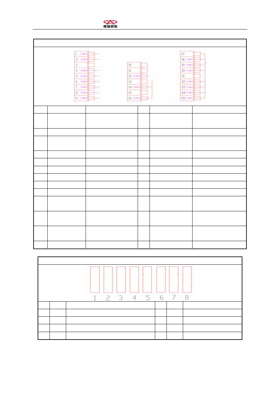
C119 ABS Controller
Pin Color
Description Pin
Color
Description
1
0.5 Black
Front left wheel speed
sensor “+”
2
0.5 Green
Front left wheel speed
sensor “-”
3
Empty
4
0.5 Red/white
Power supply
5
0.5 Blue
Rear right wheel speed
sensor “+”
6
0.5 Brown
Rear left wheel speed
sensor “-”
7
0.5 Brown/white
Diagnose connector
8
2.0 Brown
Earthing
9
2.5 Red
Power supply
10
Empty
11
Empty 12
0.5
Yellow/white
Sleeve
stub
13
Empty 14
0.5
Yellow/white
Sleeve
stub
15
Empty
16
0.5 Gray/black
ABS fault indicator light
17
Empty
18
0.5 Brown/blue
Braking light switch
19
0.5 Black
Front right wheel speed
sensor “+”
20
0.5 Brown
Front right wheel speed
sensor “-”
21
Empty
22
0.5 Black
Rear right wheel speed
sensor “-”
23
0.5 Green
Rear left wheel speed
sensor “+”
24
2.5 Brown
Earthing
25
2.5 Red
Power supply
C120-1 Fuse Instruction
Pin Color
Description
Pin
Color
Description
1
Left high beam fuse 10A
2
Left parking light fuse 10A
3
Left low beam fuse 10A
4
Right high beam fuse 10A
5
Right parking light fuse 10A
6
Right low beam fuse 10A
7
Vehicle speed, camshaft, ignition coil 10A
8
Fuel pump relay 15A