Chery A15. Manual - part 112
Approximate temperature of battery
Minimum voltage (V)
21
°C(70°F) 9.6
16
°C(61°F) 9.5
10
°C(50°F) 9.4
4
°C(39°F) 9.3
-1
°C(30°F) 9.1
-7
°C(19°F) 8.9
-12
°C(10°F) 8.7
-18
°C(0°F) 8.5
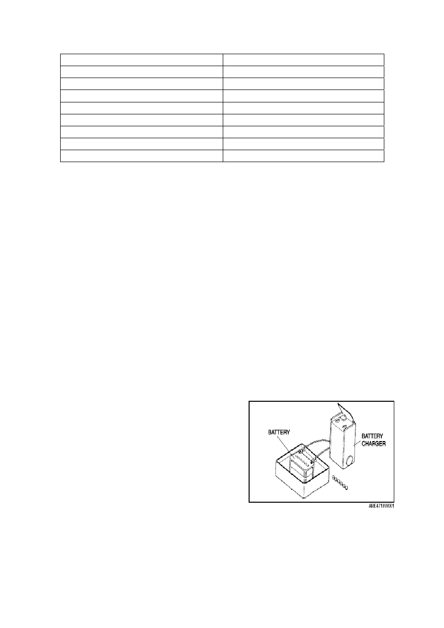
CHARGING OF BATTERY
Warning: Keep the battery away from any flammable materials. If not, the gas emitted
from the battery liquid that is easily flammable may cause severe injury or
even death of people.
Note: In order to prevent the battery and other components from being damaged, all
attached devices and the generator should be shut down before maintaining or
charging the battery.
REMOVAL/INSTALLATION OF THE GENERATOR
Warning: When connecting wires of the battery are in on-state, and at this time if you
contact the generator terminal with the car body, sparks will happen. It may
cause body injury, fire and the sparks may damage electrical components.
Therefore, before carrying the following operation, you must disconnect the
negative grid of the battery first.
Note:
—
The negative grid of battery should be
disconnected first during removal, and should
be connected last during installation. It will
avoid the damage to battery or any other
electrical component.
—
In order to prevent the battery or other
components from being damaged, all auxiliary
devices and the generator should be shut down
during maintaining or charging the battery.
—
Place the battery in water basin so as to
prevent it from overheating; water level of the
basin should be about half of the battery
height. During charging, disconnect connectors
of the battery and make sure to keep the upper
T-5