Chery A15. Manual - part 95
DISASSEMBLY AND ASSEMBLY OF
REAR SEATS
Disassembly:
1. Pull out the rear adjusting lever so as to
disconnect the seat, and fold it forward.
2. Remove the guard plate for the seat cushion
and car fastening bolts.
3. Loosen the fastening bolt between the seat
of the rear beam and the car floor.
Assembly:
Assembly is the reverse of disassembly.
The tightening torque of the specified bolt for
the seat cushion assembly is 2.5±0.5mm.
REMOVABLE REAR SEAT
DISASSEMBLY AND ASSEMBLY OF THE
ENTIRE OR THE PART OF SEAT
Pull the adjustment lever of the rear seat
upwards and fold it until it disconnects with
the front-folded part of the seat.
Remove the guard plate on the fastening bolt
between the seat and car.
Loosen the fastening bolt of the corresponding
position on the rear beam of the car.
When installing, the steps are the reverse of
disassembly.
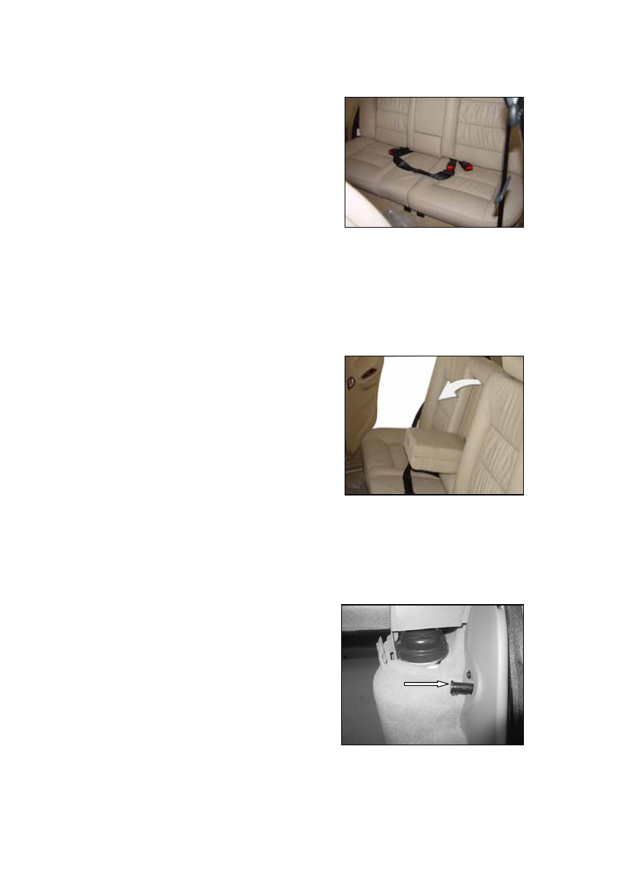
DISASSEMBLY AND ASSEMBLY OF
BUILT-IN FITTING ON THE BACK
UPPER SIDE OF REAR SEAT
Disassembly:
Loosen the fastening bolt of the flexible pin of
the built-in fitting.
Assembly:
Assembly is the reverse of disassembly.
S-30