Chery A15. Manual - part 66
 

  Index      Chery     Chery A15 - service repair manual


Search            


Content   ..  64  65  66  67   ..


Chery A15. Manual - part 66


----

The connection between the lower 
control arm of the suspension and the 
steering knuckle is clearance fit. 
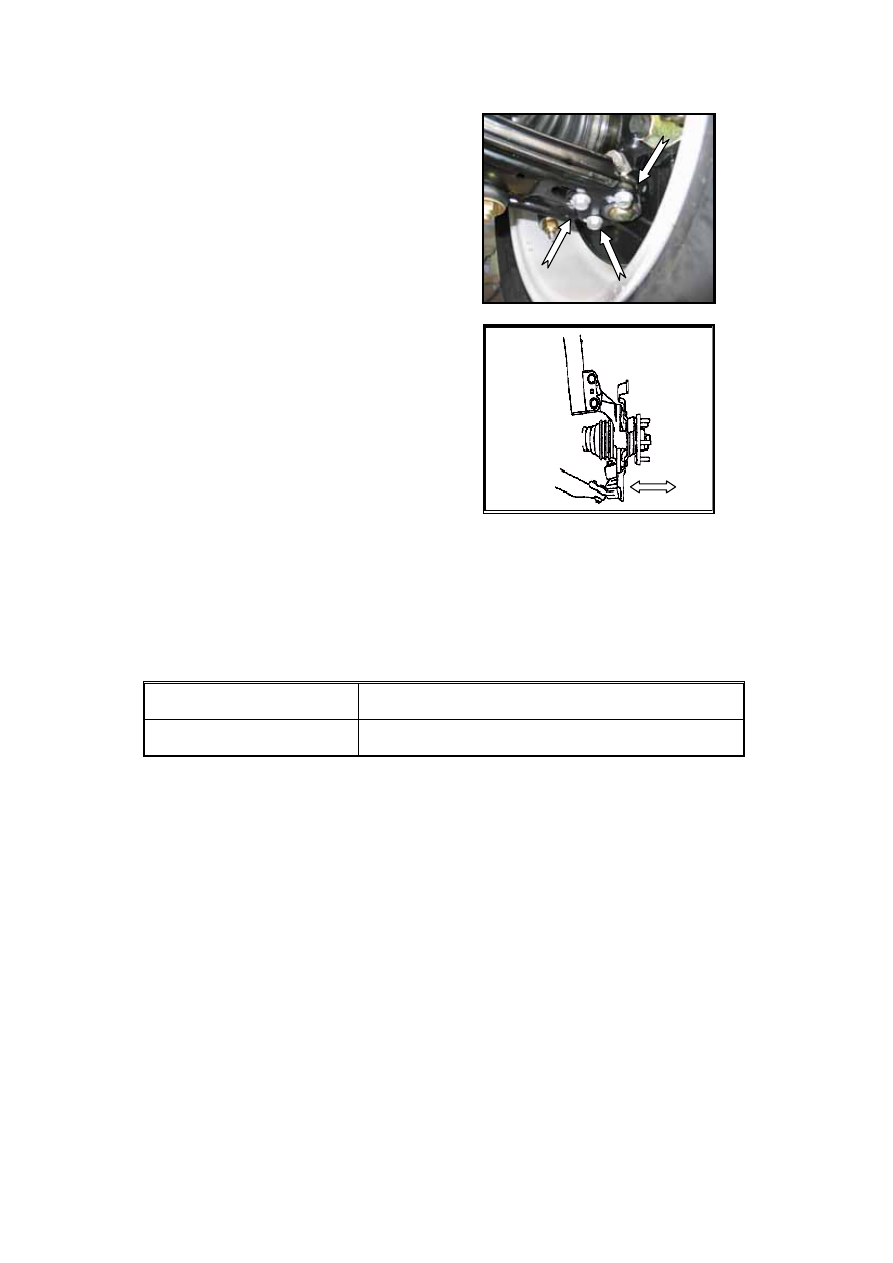
Loosen the joint bolt, move the wheel 
and adjust the camber. 


Check the front wheel toe-in 

Toe-in (general) 

Car No. 

Chery A15LHD 

Front wheel toe-in 

0′±10′ 

Tightening torque of toe-in: 55±5N•m. 

Adjust the toe-in 

Optical tester or mechanical toe-in adjuster can be used to adjust the toe-in. 

----

According to the tester’s requirement, make the wheel alignment well before the 
adjustment; 

----

Loosen the lock nut and the elastic cover snap ring of the right steering tie rod, and 
then screw the toe-in adjusting rod till the length of the rod reaches the specified 
value. 

----

Tighten the lock nut and reinstall the elastic cover snap ring. Check whether the lock 
nut is tightened enough and cover is in the correct position. 

----

After adjusting the front wheel toe-in, check whether the steering wheel is level. If not, 
loosen the lock nut of steering wheel, and then adjust to the level position. The 
tightening torque of the steering wheel lock nut is 55±5N•m as required. 


M-12

FRONT SUSPENSION 


The functions of axle and suspension system include receiving the torque generated by 
engine and passed via transmission system; producing the traction force between the road 
surface and the vehicle body through the adhesive force between the driving wheel and the 
ground in order to keep the whole vehicle steering normally; passing and bearing the 
counterforce on the wheel from different directions and relieving the impact and shake from 
the road to the vehicle body in order to ensure the stability and maneuverability of the whole 
vehicle. The front suspension is composed of the sub-frame, lateral stabilizer bar, control arm 
and etc.


REMOVAL AND INSTALLATION OF THE FRONT SUSPENSION 
 

----Loosen the opening of the joint bracket of 

the front shock absorber assy and clip it 
to the bolt of the steering knuckle 
arm(tightening the lock nut to 80N•m), 
(shown as the picture) 


----Remove the joint bolt of the control arm 

assy and the front steering knuckle with 
braker, and then release the front control 
arm assy. 

Inspection of the control arm: check the 
situations of the damage crack and bend. 


----Loosen the four bolts amounted on the 

sub-frame of the steering gear with tie rod 
assy (the specified tightening torque is 
30N•m). (shown as the picture) 


M-13


----Suspend the engine and transmission assy, 

loosen the bolts at the two supporting 
points from the engine and transmission 
to the sub-frame. 


Caution: The removal process is extremely 
dangerous which could cause serious 
damage or even death. Please make sure the 
power assy is well fixed. 


----Loosen the lock nut of the left-right 

steering tie rod and the steering knuckle 
arm, knock from one side to pry the ball 
joint out of the steering knuckle arm (The 
tightening torque is specified as 35±3 
N·m). 


----Stand the front sub-frame by jack and 

loosen the four long-short bolts of the left 
-right sub-frame with the cross beam. 
(The tightening torque is specified as 
130±10 N·m). 


Caution: The removal of the cross beam is 
extremely dangerous. The drop of cross 
beam components could cause serious 
damage or even death. Please make sure 
that the jack has supported fully the cross 
beam components before the removal. 


M-14

OVERHAUL OF THE FRONT SUSPENSION 

Installation of the front axle 


Cherry adopts the divided steering drive axle as 
the front axle. The suspension is the model of 
shock absorber (also called MacPherson) 
independent suspension. The front suspension 
of A15RHD model has the functions of both 
driving and steering. The top of the suspension 
is connected with the vehicle body while the 
bottom with the steering knuckle. The wheel 
camber is adjusted through the joint bolt of the 
suspension the steering knuckle. The sub-frame 
enhances the stability and comfortability of the 
vehicle through the connection of the control 
arm ball pin and the hinge by adopting the 
elastic components.   


Overhaul of the front suspension 

----When overhaul the front suspension, please 

do not weld or remodel the support and 
guide devices of the front suspension. 

----Use the special purpose tools to remove the 

joint bolts or nuts. Make sure the 
tightening torque fits the specified value. 

----When install the sub-frame to the vehicle 

body, the sequence of tightening the joint 
bolts is the rear left bolt, the rear right 
bolt, the front left bolt and the front right 
bolt last. 

----Check the position of steering wheel and 

measure the data of front wheel 
alignment after installation. 

Overhaul of front shock absorber assy 

----Structure of the front shock absorber 

(shown as the illustration) 


Illustration. The installation


of the

front strut assy   
1-front shock absorber assy
2-front dust cover 
3-front bumper block4-slotted nut
40N•m 
5-bearing and vibration isolator assy 
6-front spring top tray       
7-washer   8-front coil spring 

M-15


Content   ..  64  65  66  67   ..