Chery A15. Manual - part 20


  Index      Chery     Chery A15 - service repair manual


Search            


Content   ..  18  19  20  21   ..


Chery A15. Manual - part 20


THERMOSTAT  

Disassembly: 

——To unscrew 3 M6×40 bolts and then demount the 

bolts;  

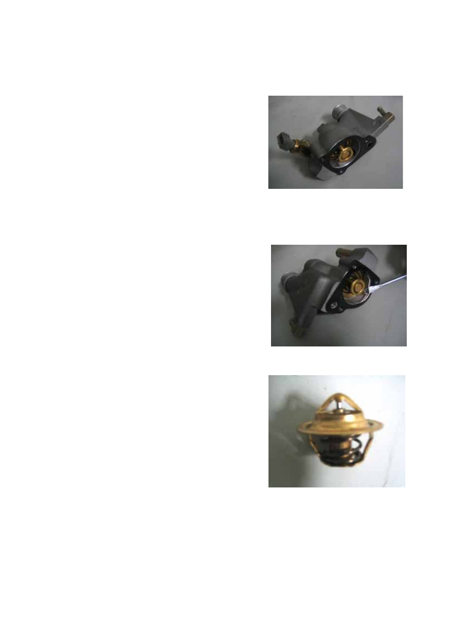
——To demount thermostat chassis and thermostat 

assembly.  


——To pry out the spring clamps by using chisel or 

screwdriver.  


——To take the thermostat out;   

——To clean up the thermostat; 


E-7

——To take the seal ring out, and replace it if it being 

worn and torn.   

——To demount the gasket from the thermostat chassis. 

To replace with new gasket if it is worn and 

torn, and allow no repeated use.)


——To measure the thermostat opening temperature 

under hot water.   


Assembly: 

——To clamp the thermostat and then put the gasket 

into the thermostat aperture.   

——To install thermostat (the side with spring facing 

outward). 

——To embed spring clamp to ensure the clip within 

the thermostat chassis slot; 

——To mount new gasket onto thermostat chassis; 

——To mount the thermostat chassis and thermostat 

assembly into the aperture at the rear side of engine 
cylinder head, and screw up the bolt by hand to 
9—12N.m.


E-8

WATER TEMPERATURE SENSOR 

Disassembly: 
——To demount water temperature sensor (at the 

exhaust pipe flank and under the lifting eye).


Assembly: 
——To apply Letai 243 glue on the screw thread, 

screw up the bolt to 7.0—10.0Nm before 
installation.


Checking:


Water temperature sensor is a negative temperature coefficient sensor, which is composed of 

a thermal resistor. The resistance value of the resistor shall decrease as the engine temperature 
rises. The variation is detailed in the following table:   


Temperature (°C) 

Resistance Value (Ω) 

-20 29,125 

-10 16,660 

0 9,790 

+20 3,748 

+25 3,000 

+60 747 

+80 377 

+100 204 

+120 117 


COOLING FAN 


Disassembly:


——To disconnect the negative terminal of battery;   


E-9

——To demount the matching plug of the cooling fan.


——To remove the fastening self-tapping screw from 

the cooling fan. 


——To take the cooling fan out.   


Assembly: 

——To assemble the cooling fan according to the 

disassembly order (the tightening torque of 
self-tapping screw is 1.8~2.2Nm) 


——To start up the engine and check if the cooling fan 

is under normal operation.


Guideline For Disassembly: 

——During the disassembly process, you should pay 

more attention not to pull A/C pipe to a large extent, 
otherwise the A/C pipe shall crack and deform. 


E-10


Content   ..  18  19  20  21   ..