Chery A11. Manual - part 26


  Index      Chery     Chery A11 - service repair manual


Search            copyright infringement  


Content   ..  24  25  26  27   ..


Chery A11. Manual - part 26


CAC Gasoline Engine Maintenance And Servicing Manual 

59 

The intake manifold ‘s air may be preheated by the electrical heater as well as by coolant. As the coolant’s 

temperature is lower than 60°, the electronic heater will be energized to facilitate the cold starting. 
 

The electrical heater’s energizing or deenergizing is controlled by the intake preheating switch and relay. 
The  intake  preheating  switch  is  installed  in  the  M22  bolt  hole  in  the  thermostat  seat(with  the  hole   

plugged by plug screw for carburetor engine). 

The intake preheating switch’s operation parameters: 

Switching off temperature: 63±4° 
Switching on temperature:  ≥52° 
Operation voltage: 6—24V 
Electrical heater parameters:… 
Voltage: 15V 
Initial current:  ≤75A 
Cold resistance: 0.2—0.4Ω 
temperature after 12-second energizing:  >60℃ 
temperature after 180-second energizing:  >135℃ 

 
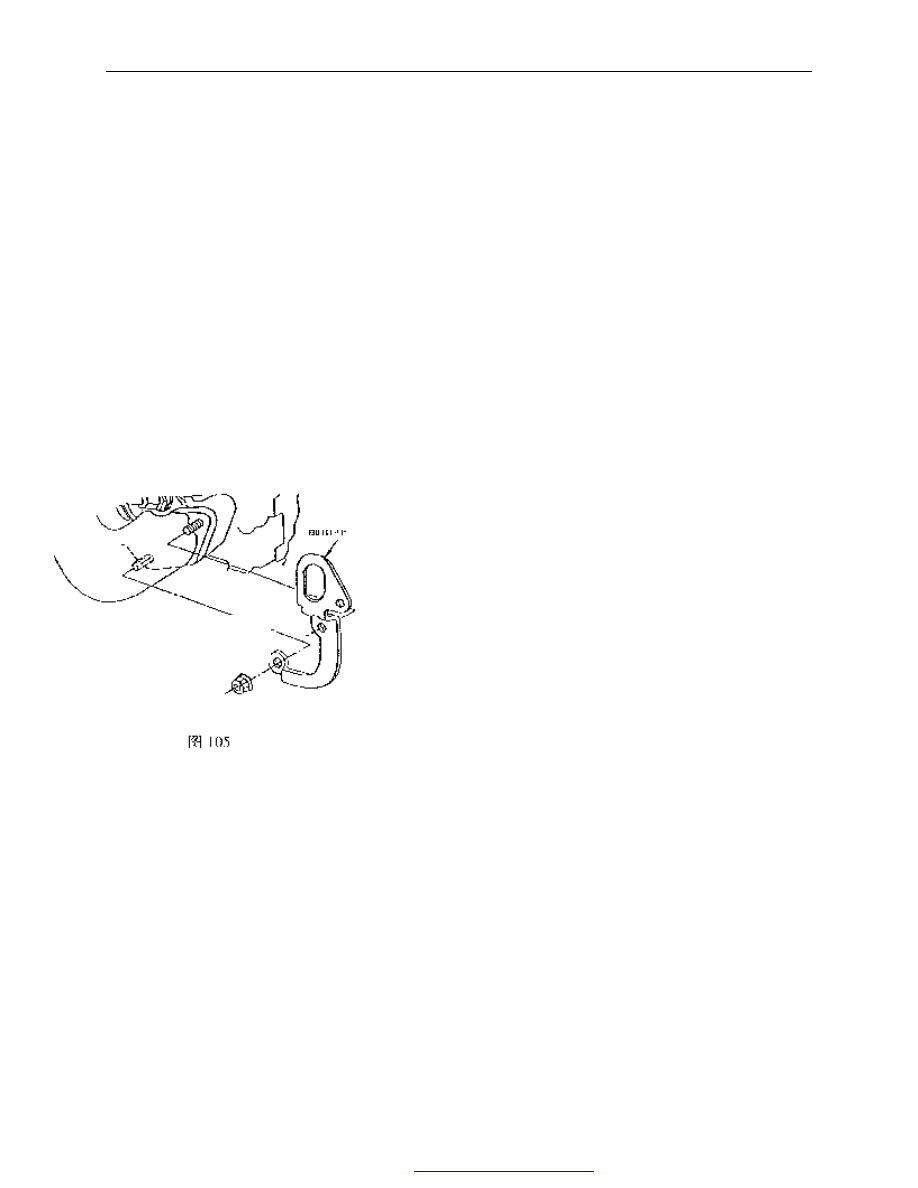
3.3 Removal and assembly for the intake manifold assembly and front lifting lug: 

Removal: 

——Loose  and  remove  two  M8  lock  nuts  from  the  right  front 
lifting lug. 
——Remove the front    lifting lug. 
——Loose and remove the remaining four M8 lock nuts. 
——Remove the intake manifold. 
——Remove the intake manifold sealing gasket. 
——Remove six studs with equal length using two M8 nuts. 
 
Assembly: 
——Apply lotite sealant 201 on the cylinder head bolt threads and 
screw six studs into the cylinder head. 

——Assemble 

the 

new sealing gasket onto the studs. 

——Install  the  intake 

manifold assembly. 
——Install the front lifting lug onto the right two studs. 

——Finger screw in nuts and tighten to16-20Nm. 


Fig. 105 

Front lug 

PDF 文件使用 "pdfFactory Pro" 试用版本创建  


www.fineprint.com.cn

CAC Gasoline Engine Maintenance And Servicing Manual 

60 

4. The removal and assembly for the exhaust manifold, heat insulation cover and rear lifting lug: 


Removal: 
-Loose and remove the M12×25 allen screw, and remove 
the rear lug . 
-Loose  and  remove  two  M8×12  screw  and  remove  the 
heat insulation cover . 
-Loose and remove 8 M8 lock nuts and washers.-remove 
the exhaust manifold. 
-Remove  the  exhaust  manifold  sealing  gasket.-Remove 
eight M8 studs of same length. 
 
Assembly: 
-screw in 8 M8 studs of same length and tighten them with 
two nuts. 
-Assemble the new exhaust manifold sealing gasket. 
-Install the exhaust manifold. 
-Put the washers onto the studs and tighten lock nuts with 
hands, tightening torque is 14-17Nm . 
-Assemble the  heat insulation cover and tighten two bolts 
with hands ,tightening torque      is 14-19Nm . 
-install  the  rear  lug  and  tighten  allen  screw  with  hands  , 
tightening torque is 50-60Nm. 


5.  for  oxygen  sensor  and  3  way  catalyst  Converter,  See 
“CAC480M Engine’s single port injection system”   

Bolt 

insulating 

cover 

exhaust 
manifold 

Fig.106 

Flat washer 
hexagonal nut 

Water  temp. 
sensor 

Sealing gasket 

PDF 文件使用 "pdfFactory Pro" 试用版本创建  


www.fineprint.com.cn

CAC Gasoline Engine Maintenance And Servicing Manual 

61 

16】  Positive Crankcase Ventilation(PCV)system of engine. 

1.  Description for PCV system of the Carburetor engine: 

PCV system is a closed system. 

The  leaking  air  of  piston  from  the  Crankcase  goes  to  the 

cylinder head cover through the PCV hose. The exhaust gas enters 
the intake  manifold    passing the 3-way pipe after throttled by the 
absolute  pressure  pipe  connector.  The  gas  in  the  crankcase  enter 
the 3 -way pipe through the guide cover to ventilate the crankcase. 

The  PCV  system  includes  oil  baffle  assembly,  PCV 

pipe—cylinder  block,  absolute  pressure  transmission  hose 
connector, 3-way connector, valve chamber cover, connecting hose, 
ventilation  hose.  See  the  above  for  Removal  and  Assembly  of  oil 
baffle assembly and valve chamber cover assembly. 


2. Description for PCV system of 480M engine 


2.1    Description  of 
PCV system. 

The 

PCV 

system  is  a  closed 
system. 

The  leaking  air 

of piston goes to the 
rear  cylinder  head 
cover 

from 

the 

Crankcase  through 
the  PCV  hose.  PCV 
valve  is  connected 
to 

the 

intake 

manifold. Meantime, 
a  Ф15  hose  in  the 
front  of  the  valve 
chamber 

cover 

assembly 

is 

connected  to  the 

guide  cover  and  PCV  valve  by  the  3-way  connector 
through a hose. 

The PCV system includes oil baffle 

assembly, PCV pipe——cylinder block, 
PCV hose, PCV valve, 3-way connector, 
valve chamber cover, connecting hose, 
and ventilation hose. 

Connection 
hose 

3 way connector 

Absolute  pressure  transmitting  hose  connector 
in intake gas hose


PCV valve 

3 way connector 

C

o

n

n

e

c

to


g

u

id

e

 c

o

v

e

Connect  to  cylinder  cap 
cover 

C

o

n

n

e

c

to


in

ta

k

e

 g

a


C

o

n

n

e

c

to


g

u

id

c

o

v

e

Connection hose   

C

h

a

m

b

er


c

o

v

e

c

a

p


Clip   

Fig. 107 

PDF 文件使用 "pdfFactory Pro" 试用版本创建  


www.fineprint.com.cn

CAC Gasoline Engine Maintenance And Servicing Manual 

62 

2.2 PCV valve’s function: 

under the low speed condition, the  vacuum  of intake  manifold 

is very high, which keep the valve closed, and only a small opening 
exists  to  allow  the  gas  pass  through. Therefore  it  won’t  change  the 
mixture  rate.  Under  high  speed  condition,  the  vacuum    of  intake 
manifold decreases, and the spring forces the valve to open to allow 
more gas in the crankcase flow into intake manifold. 

the  PCV  valve  is  designed  to  open  fully  enough  to  allow  the 

gas  exhaust  from  the  crankcase  under  high  speed  or  low  speed 
conditions. 


【17】. Fuel supply system of the carburetor engine. 

1. 

Fuel supply system of the carburetor engine. 

1.1  Description 
of 

the 

fuel 

supply system. 

The  fuel  in 

the  tank  flows 
into  oil  filter 
pumped  by  the 
fuel  pump  and   
goes 

into 

carburetor  after 
being 

filtered 

through 

fuel 

pump 

amount  of  fuel 
returns  to  the 
tank 

through 

return pipe . 


1.2 Removal and assembly of the fuel pump: 
——Remove two M8 lock nuts. 
——Take out the fuel pump. 
——Remove the fuel pump sealing gasket. 
——pull out the push rod. 

From crankbase 

From crankbase 

the operation condition of low speed-high vacuity 

to intake manifold   

the operation condition of high speed- low vacuity 
                                Fig.109   

to intake manifold 

Engine   

Fig.110 schematic drawing of fuel supply system for engine 

 gasoline filter 3. gasoline pump 

Fig. 111 

PDF 文件使用 "pdfFactory Pro" 试用版本创建  


www.fineprint.com.cn


Content   ..  24  25  26  27   ..