Chery A series. Manual - part 133
 

  Index      Chery     Chery A series - service repair manual


Search            copyright infringement  


Content   ..  131  132  133  134   ..


Chery A series. Manual - part 133


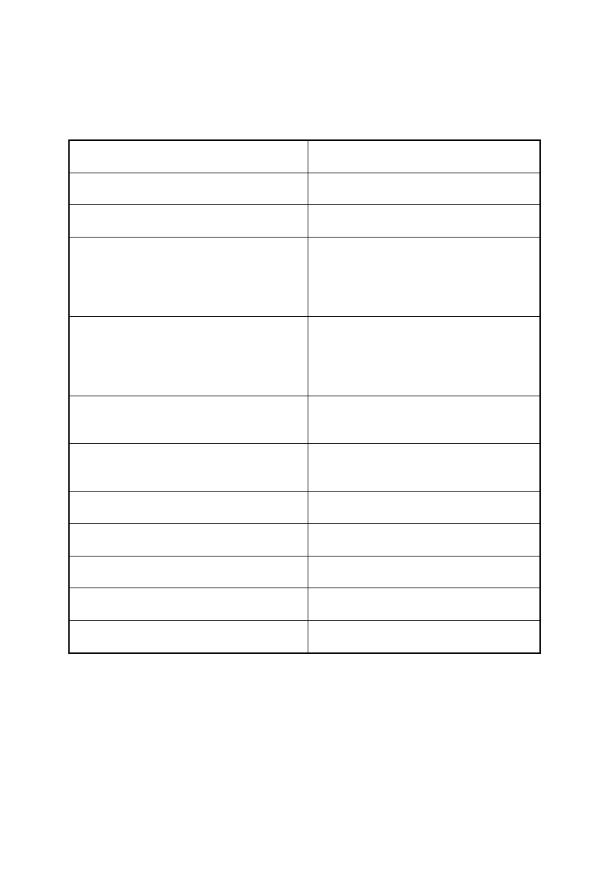
 Swash 

Plate 

Number of cylinders 

Cylinder diameter (mm) 

29.3 

Travel (mm) 

max 

min 


34.2 

2.2 

Displacement (cm³/r) 

max 

min 


161.3 

10.4 

Allowable maximum instantaneous speed 
(r/min) 

8000 

allowable maximum continuous speed 
(r/min) 

7000 

Coolant R134a 

Refrigerant oil (cm

3

) 115±15 

Electromagnetic clutch mass (kg) 

2.2 

Rated voltage (V) 

12 

Rated power (W) 

48 


U-15


The compressor is driven by engine crankshaft pulley via the M belt. When the shift lever 
on the A/C control mechanism is shifted to the refrigeration position, the electromagnetic 
clutch of A/C compressor engages, and the compressor pulley make the main shaft and 
swash plate rotate and then pull the rocking plate to swing. The swinging of the rocking 
plate pushes the piston to move, which creates the air pumping effect to compress the 
low-temperature and low-pressure air-state coolant into the high-temperature and 
high-pressure air-state coolant. 

The motion parts of compressor are lubricated using the sputtered refrigerant oil and the oil 
in coolant. During the operation of compressor, due to the rotation and swing of the swash 
plate, the refrigerant oil will be sputtered to anywhere. In addition, due to the intersolubility 
of coolant and oil, when the coolant flows into the compressor, it also carries a part of 
refrigerant oil which is available to lubricate the motion parts inside the compressor. 

ADJUSTMENT OF ELECTROMAGNETIC CLUTCH 

1. Use a thickness gauge to measure the clearance between the platen and A/C compressor 

pulley. 

2. Check whether the clearance is in the range specified by the technical specification. 

• If it is found that the result doesn’t conform to the requirement of technical specification, 

remove the platen, and use one or several shims to adjust the clearance. 

Clearance: 

0.6mm±0.2mm


3. Removal/Inspection of condenser 

(1). Drain off the coolant from the system (see the 

coolant recycling procedure) 

(2). Remove the front bumper and headlamp crossbeam 

assy. 

(3). Remove the fluid reservoir and the refrigeration 

pipes connecting to the condenser. 

Check the condenser: 

(1) Check the crack, damage or oily fluid leakage. 

·Replace the condenser if any failure above occurs. 

(2) Check whether the fender position is blocked by dust 
or not. 

·Clean it if blocked. 

(3) Check the bent condition of fender position. 

·Use a flat headed screwdriver to straighten the fender 


U-16


position if the bent is found. 

Installation of Condenser 

(1) Use some self-tapping screws to secure the 

condenser and radiator, and assemble the related 
screw bush and spacer, with the tightening torque 
of 6±0.6N·m; 

(2) Use the bolts (M6) and spacer to secure the 

condenser support on the front crossbeam, with the 
tightening torque of 1.5±0.15N·m; 

(3) Assemble the integrated condenser-radiator into the 

related fixing holes; 

(4) Use spacer, shim block and two nuts to fasten the 

condenser and front crossbeam, where the tightening 
torque of nut is 1.5±0.15N·m. 

The condenser is designated to cool the coolant vapor 
discharged from the compressor and condense the vapor 
to make it give off its heat and become to the coolant 
fluild. 

Chery A15LHD adopts the serpentine condenser, as 
shown in the figure. The condenser is secured with 
engine radiator in a row, and there is an axial fan, which 
is driven by a DC motor, behind them to forcedly cool 
the condenser and radiator. 

Introduction to the fluid reservoir: 

Removal/Installation (see the Removal of Condenser) 

Chery A15LHD’s fluid reservoir is located under the 
condenser (i.e., the outlet of condenser), the structure of 
which is shown in the figure. 

In fact, the fluid reservoir is a pressure container used to 
store the coolant, and it is available to delivery the 
fluid-state coolant to the expansion valve at a specified 
flow rate. The filter screen of fluid reservoir is applied to 
filter the all kinds of foreign materials from the coolant. 
The drying agent silicon oxide with powerful water 
absorptivity is filled in the drying unit, which is used to 
absorb the water content in the coolant. In addition, a 
fusible plug is also installed on the reservoir. If the poor 
heat emission of condenser or other causes result the 
rapid rise of temperature and pressure of the 


U-17


refrigeration system, the fusible plug will metal so as to 
drain off the high-temperature and high-pressure coolant 
when the temperature and pressure inside the reservoir 
reach the specified value, which protects the 
refrigeration system.


4. Introduction to the expansion valve and pressure 
switch 

1) Expansion valve 

Chery A15LHD adopts the traditional thermo-expansion 
valve, as shown in the figure, fixed on the inlet/outlet 
pipes of evaporator. 
The temperature sensor inside the expansion valve 
adjust the opening of ball valve in accordance with the 
temperature of coolant located at the evaporator outlet, 
the purpose of which is to control the flow rate of 
coolant.


2) Pressure switch 

Chery A15LHD’s A/C pressure switch adopts the 
dual-pressure (high and low pressures) and four-wire 
pressure switch which is installed on the high pressure 
pipe located at the front end of expansion valve, with 50 
PSI or more of low-pressure CLOSE  operation and 
220 PSI or more of high-pressure CLOSE operation


5. Removal/Installation and inspection of evaporator 

(1) Drain off the coolant from the system (see the 

coolant recycling procedure) 

(2) Remove the expansion valve 

(3) 

Remove the instrument panel (see the 
Disassembly/Assembly of Instrument Panel) 

(4) 

Remove the control panel trim plate, and 4 
self-tapping screws used to secure the control panel 
and console. (tightening torque of 1.5±0.2N·m) 

(5) Remove 1 bolt (M8*25) and 4 nuts secured with the 

steering crossbeam and front side respectively 
(tightening torque of 3.5±0.2N·m) from the fixed 
evaporator. 

(6)   Remove the four bolts from the evaporator. 

Inspection of evaporator: 


U-18


Content   ..  131  132  133  134   ..