Chery A series. Manual - part 131
 

  Index      Chery     Chery A series - service repair manual


Search            copyright infringement  


Content   ..  129  130  131  132   ..


Chery A series. Manual - part 131


1. Precautions for Refrigerant Concerned 

(1) To avoid the refrigerant contacting with 

your skin, wear rubber gloves and safety 
goggles while handling the refrigerant. 

(2) Handle the refrigerant concerned at a well 

ventilated location. Since the refrigerant is 
a colorless gas at room temperature and its 
density is greater than that of air, the 
refrigerant will deposit in the maintenance 
location, which may easily cause the 
maintenance personnel choked. 

(3) Do not allow the refrigerant to contact with 

fire. Otherwise it may generate the toxic 
gas. 

(4) The O-ring can be applied once only. 

(5) 

Chery model-A15LHD adopts the 
refrigerant R134a which cannot be 
interchanged with R12.    Also compressor 
oils cannot be mixed. During the course of 
handling, any tool that has touched certain 
kind of refrigerant must not touch any other 
kind of refrigerant.   


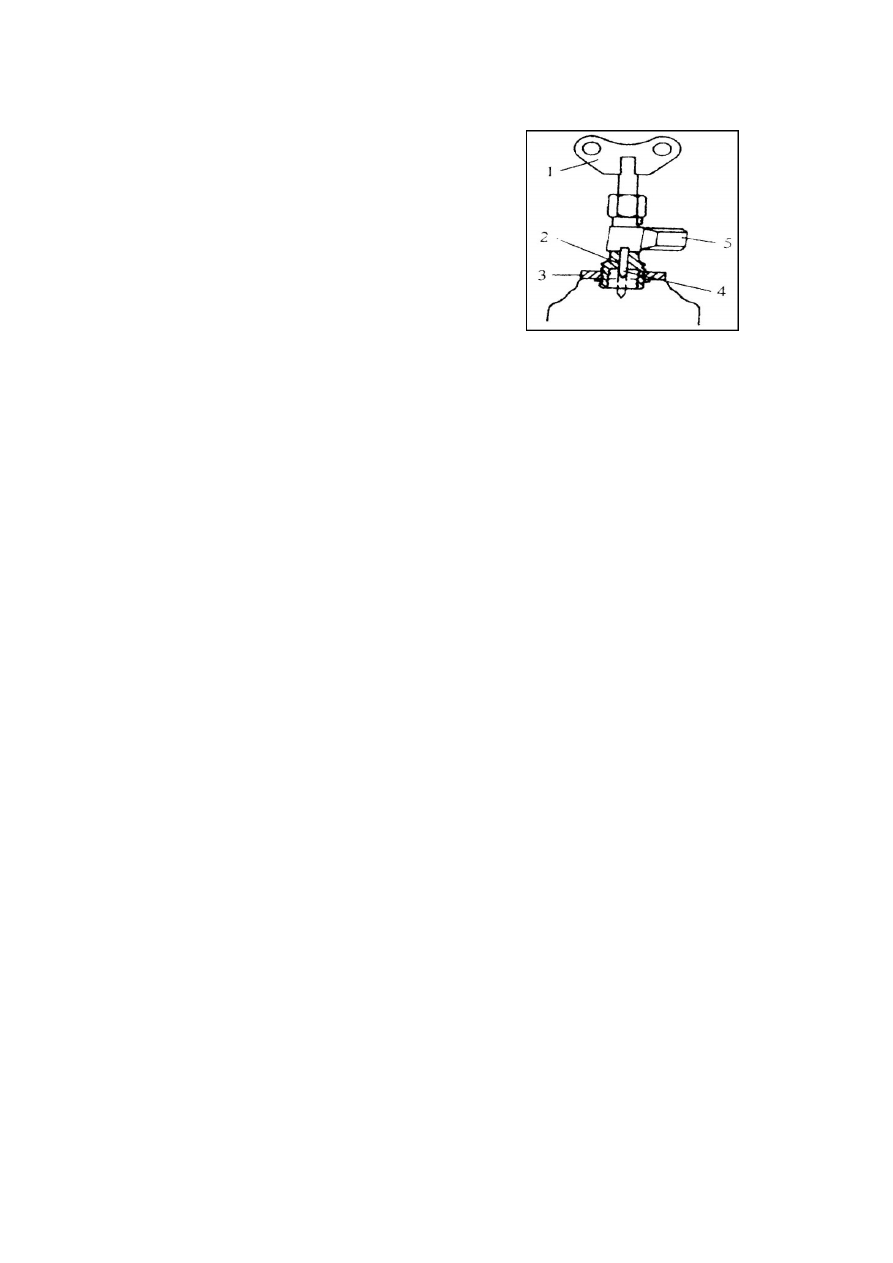
Refrigerant Tank Unlock Valve 

1-Butterfly Handle   

2-Refrigerant Tank Refilling Valve 

 3-Plate-shaped Nut   

4- Needle Valve   

5-Refilling Valve Joint 

2

. Method to Refill Refrigerant 

If the 400g tanked refrigerant is required, a 
refrigerant tank unlock valve shall be applied 
(shown in the figure). The operation 
procedures are as follows:   

(1) Before the unlock valve is installed on the 

refrigerant tank, turn the butterfly handle 1 
in the counterclockwise direction till the 
needle valve returns back completely. 

(2) 

Turn the plate-shaped nut 3 in the 
counterclockwise direction to lift it up to 
the highest position, and then tighten the 
valve and the dummy club at the center of 
refrigerant tank. 

(3) Install the intermediate filling hose of 

manifold pressure gauge on the joint 5, and 
then turn the plate-shaped nut in the 


U-7


clockwise direction and tighten it by hand 
as possible.   

(4) 

Turn the butterfly handle 1 in the 
clockwise direction to make the valve 
needle 4 in its front end punch a small hole 
in the dummy club of refrigerant tank. 

(5) 

Turn the butterfly handle 1 in the 
counterclockwise direction, which the 
refrigerant will flow into the manifold 
pressure gauge along the charging hose. 

(6) Then turn the butterfly handle 1 in the 

clockwise direction to the lowest position, 
and it can close down the refrigerant tank 
again. However, do not detach the unlock 
valve, otherwise the refrigerant inside the 
tank will leak out. 


3. Refrigerant Refilling Procedures 

(1) Connect the manifold pressure gauge to 

the refrigerant tank, shown in the picture 
below. 

(2) Unscrew the handle of unlock valve 2 in 

the counterclockwise direction to enable 
the refrigerant to enter the intermediate 
charging hose. In this case, do not open the 
handle valves in the both sides. 

(3) Unscrew the nuts of intermediate hose of 

manifold pressure gauge, and then tighten 
the nuts of intermediate hose after the air 
inside the intermediate hose are drained 
when you see the white refrigerant gas 
overflow and heard the “fizzle” sound. 

(4) Turn on the high-pressure manual valve 4, 

shown in the figure below, stand the 
refrigerant tank 1 upside down so as to let 
the refrigerant in liquid-state charge into 
the refrigeration system. In this case, do 
not switch on the A/C unit to prevent the 
refrigerant from returning back to the tank. 


HIGH-PRESSURE 

SEVICE VALVE

REFRIGERATION DEVICE

RECYCLING 

RECEIVER 

LOW-PRESSURE 

SEVICE VALVE


U-8


200 g or more refrigerants shall be charged 
every time, and turn the compressor 
several times by hand after the completion 
of charging. 

(5) Turn off the high-pressure manual valve 4, 

shown in the figure below, and turn on the 
low-pressure manual valve 3 to let the 
refrigerant in gas-state charge into the 
refrigeration system. The refrigerant 
charged from the low-pressure manual 
valve must be gas-state. If it is liquid state, 
the liquid hammer phenomenon may 
appear to damage the compressor. Turn off 
the low-pressure manual valve when the 
reading of low-pressure gauge reaches 
2.8X10

Pa. 

Refrigerant Refilling   
Regulated amount:R134a,850±25g 


4. Leak Check of Refrigeration System 

Three effective methods can be used to check 
the air tightness of refrigeration system: check 
with electronic leak detector, soap solution and 
halogen leak detector.   

1) Check with Electronic Leak Detector 

As shown in the figure, connect the power 
supply connector 2 of electronic leak detector 
1 to the power supply, and move probe 3 
slowly (30 mm/s), which should be placed 3 
mm away from the check point. And if any 
alarming sound is emitted, it means there is a 
leak phenomenon occurred at that place. 

2Check with Soap Solution 

Apply the soap solution to the possible leak 
position. Observe whether air bubbles appear. 
If there are air bubbles, it indicates a leaking 
accident occurs.                

3Check with Halogen Leak Detector 

The inspection procedure is described below: 

(1) Check the liquid propane capacity in the 


1. Electronic leak detector.   

2. Power supply connector.   

3. Probe 

If the leakage occurs at the joints

of refrigeration pipes, the relevant

O-rings shall be replaced. 


U-9


reservoir.  

(2) Tighten the propane reservoir 16 to the 

leak detector.   

(3) Insert a lighting match into lighting device 

9, and then slowly turn the adjusting 
handle 14 in the counterclockwise 
direction till the torch is lit. 

(4) Adjust the flame to smallest. The smaller 

the flame, the more sensitive to the leak of 
refrigerant.  

(5)Move suck pipe 3 to the possible leak 

position.  

(6) Observe the change of flame color. The 

flame has no color if there is no leakage. 
The flame is tint green if there is very 
small leakage or be blue if there is 
relatively big leakage, and it will become 
purple if there is too much leakage.


5. Methods of Refrigerant Oil Charging 
There are two methods for refrigerant oil 
charging: direct charging method and vacuum 
inhaling method. 


1Direct charging 
Remove the oil charging plug 1, and charge 
the specified model of refrigerant oil. 


2Vacuum inhaling 
Vacuumize the refrigeration system to 30psi, 
and then start to charge the refrigerant oil, the 
procedures of which are as follows: 

(1) Turn off the high-pressure manual valve, 

and turn off the auxiliary valve. 

(2) Remove the high-pressure side hose from 

the manifold pressure gauge, and insert 
the hose into the oil cup. 

(3) Turn off the auxiliary valve to inhale the 

refrigerant oil into the refrigeration system 
from the oil cup. 

(4) When the refrigeration oils in the cup are 

nearly evacuated, immediately turn off the 


Vacuumizing and Charging the Refrigeration Oil

Oil cup 

High-pressure pipe 

High-pressure manual valve

Low-pressure side hose

Air return 

Air exhaust 

auxiliary valve

High-pressure side hose 

Low-pressure manual valve

High-pressure gauge 

Low-pressure gauge

Vacuum pump


U-10


Content   ..  129  130  131  132   ..