Chery A series. Manual - part 61
 

  Index      Chery     Chery A series - service repair manual


Search            copyright infringement  


Content   ..  59  60  61  62   ..


Chery A series. Manual - part 61


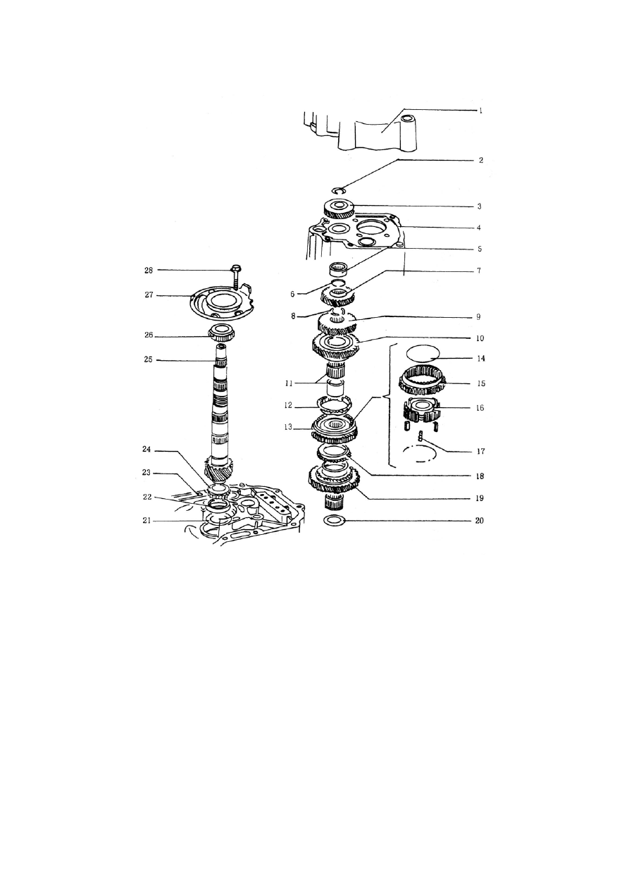
RESOLUTION GRAPH OF OUTPUT SHAFT 


1. Rear housing    2. 5

th

 Driven gear snap ring 3. 5

th

Driven gear 4. Transmission housing

5. Needle bearing    6. 4

th

 Driven gear snap ring    7. 4

th

 Driven gear    8. 3

rd

 Driven gear

snap ring    9.3

rd

 Driven gear 10. 2

nd

 Driven gear 11. 2

nd

 Driven gear and bushing 12. 2

nd

Synchronizer ring 13. 1

st

-2

nd

 Synchronizer assembly    14. Steel spring 15. 1

st

-2

nd

 Gear

sleeve 16. 1

st

-2

nd

 Hub 17. Gate 18. 1

st

 Synchronizer ring    19. 1

st

 Driven gear    20. 1

st

Needle bearing snap ring    21. Adjustment shim  22. Front bearing external ring  23.
Clutch housing  24. Output shaft front bearing 25. Output shaft 26. Output shaft
intermediate shaft  27. Intermediate bearing pedestal    28. Bearing fixing bolt Output
shaft break down


J-36

ADJUSTMENT TABLE 

Adjustment items: 

——During the repair of 

transmission assembly, you 
should think about to adjust 
the output shaft or differential 
assembly installing dimension 
when you change any of the 
below element. 

——In order to avoid the 

ungrateful work we provide 
the right table to you.


Adjusted items 

Changed parts 

Output 

shaft 

Differential

Transmission housing 

No 

Adjust 

Clutch housing 

Adjust 

Adjust 

Differential cone bearing

No 

Adjust 

Output shaft 

Adjust 

No 

Output shaft intermediate 

bearing pedestal 

Adjust No 

Differential housing 

No 

Adjust 

Output shaft intermediate 

bearing 

Adjust No 

Output shaft front bearing

Adjust 

No 


J-37

ADJUSTMENT OF OUTPUT SHAFT 


Adjustment: 

——You need adjust the thickness of the output 

shaft shim after you replaced any part of 
clutch housing,output shaft,output shaft 
intermediate bearing pedestal, output shaft 
intermediate bearing or output shaft front 
bearing. 

——See the picture, insert adjustment shim with 

0.65mm thickness, and press front bearing 
external ring of output shaft to bearing 
pedestal. 


— — Insert the output shaft assembly, put on 

bearing pedestal and fasten with 40Nm 
moment. See the picture.


Special Tool

Special Tool


J-38

CALCULATE THE THICKNESS OF THE ADJUSTMENT SHIM 


— — Put a platform benchmark on the clutch 

housing, and put a dial indicator with 
magnetic base on the benchmark. Set to 
zero when the pre fasten force is 1mm. 
Move the input shaft up and down 
according to the arrowhead direction, read 
and record the indication of the indicator. 

Main points: 

——During measuring, do not roll the output 

shaft otherwise the bearing will fall down 
and get wrong measuring value.


Disassembly: 
——For bearing pre fasten it needs thickness of 

the adjustment shim 0.20m; if the reading of 
the dial indicator is 0.30mm, and the 
thickness of the shim put in advance is 
0.65mm, then the thickness of the adjustment 
shim should be 0.20mm+0.30mm+0.65mm 
=1.15mm. 

——See the picture, screw off bearing plate bolt 

and take out output shaft. 

——Take out front bearing external ring of output 

shaft. 

——Take out the original adjustment shim.


J-39


Content   ..  59  60  61  62   ..