Chery A series. Manual - part 51


  Index      Chery     Chery A series - service repair manual


Search            copyright infringement  


Content   ..  49  50  51  52   ..


Chery A series. Manual - part 51


ASSEMBLY AND ADJUSTMENT OF CLUTCH CABLE 


·Put dust cap up and screw jam nut (11) and 

adjustment bushing (12) to the upper end 
(make the adjustment travel L minimum) 
so as to facilitate the assembly of clutch 
cable. 

·Coat a little lubricant on the assembly 

fitting surface of clutch cable. 

·Put clip (1) across the guiding cylinder of 

clutch pedal on the front brattice to 
connect the clutch pedal. Make sure that 
washer (3) and end face of guiding 
cylinder of clutch pedal are spliced. 

·Make butt end (18) fixed by bracket after 

across the slot in release arm of 
transmission and rubber cushion through 
the upper face of transmission. 

·After the assembly, uplift the segregation 

arm of transmission by hand and adjust the 
adjustment bushing (12) down at the same 
time, so the 2~3mm clearance for 
segregation arm of transmission is 
available; then tread the clutch pedal for 10 
times to ensure the fitness of assembly and 
readjust the adjustment bushing to 
guarantee that the 2~3mm clearance for 
segregation arm of transmission is 
available (Remarks:For new clutch, the 
adjustment travel L of driven disk cable 
shall not be less than 18mm. See Pic.2). 

·Carry out the driving examination for the 

whole automobile. Clutch and gear shifting 
operation shall be normal. 

·Screw jam nut (11) down to close with 

adjustment bushing (12), and then put 
down dust cover (9). 


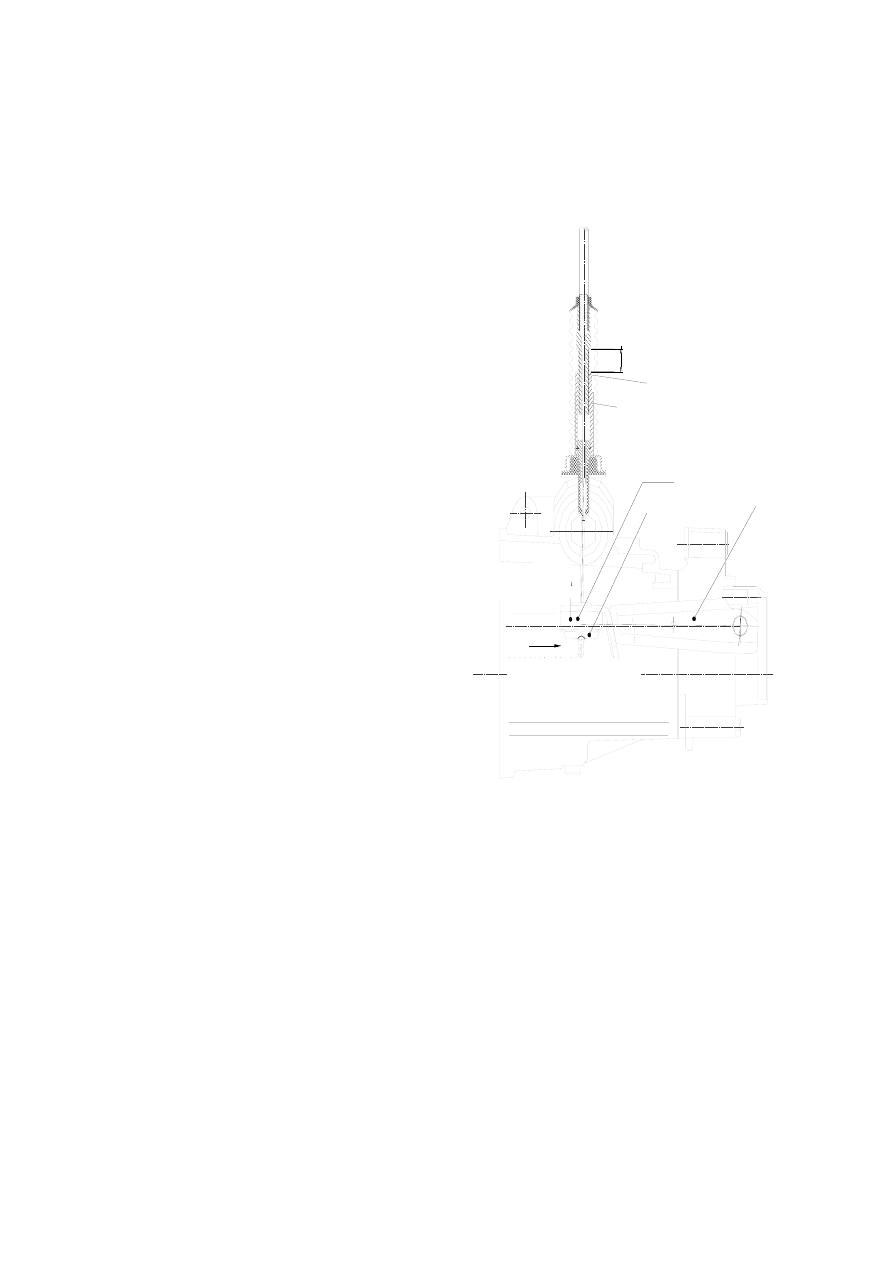
Picture 2 Sketch Map of Western
Clutch  Adjustment 

Move direction of release
disk after driven disk wear
down 

Transmission 
release pusher

When driven disk wear down,
unscrew the nuts and adjust the
bushing to a proper position   

Adjust 
bushing  

Jam nut 

Rubber cushion 

Bracket 

2~3mm free
travel 

H-4

L (adjustment travel)


CLUTCH DISASSEMBLY 


·Disassemble the transmission. 


·Unscrew 9 fixed bolts in flywheel 

cornerwise and dismount the flywheel. 


·Remove clutch plate. 


·Pry out snap ring of release disk by 

screwdriver and remove the release disk. 


·Unscrew 6 connection bolts in clutch 

pressure plate and output end of 
crankshaft, and remove the clutch pressure 
plate. 


H-5


CLUTCH OVERHAUL 

·  Clutch friction disk: measure the dent depth of 

rivet head, i.e. the distance between the rivet head 
and the friction disk surface. In case it is found that 
the depth reaches the using limit for any hole, the 
friction disk shall be changed. 

Standard value  Maintenance

Rivet head 

Dent depth 

1.5mm 

0.06in 

0.5mm 

0.02in 

·Measure the clutch disc runout using a dial indicator. 

If the runout is excessive, replace the clutch disc. 

Runout          0.8mm    max 


Clutch pressure plate: 

·Examine whether the diaphragm spring has 

abnormal wear or damage. 

·Examine whether the pressure plate has wear or hot 

point. 

·In case of any abnormality, the pressure plate shall 

be changed. The pressure plate shall not be 
disassembled into two parts: diaphragm spring and 
pressure plate. 

·Measure the clutch pressure plate runout using a dial 

indicator. If the runout is excessive, replace the 
clutch disc. 

Runout     0.25mm  max 

Flywheel: 

·Examine whether the connection surface of friction 

disk exists abnormal wear or hot point; the change 
or maintenance shall be conducted if necessary. 

·Measure the flatness of the flywheel with a straight 

edge and a feeler gauge. If not as specified, replace 
the clutch cover. 

Maximum clearance   0.05mm 

Service limit          0.15mm 


H-6

CLUTCH INSTALLATION 

Before the assembly, flywheel surfaces and pressure 
plate shall be clear and dry. 
——Assemble the pressure plate on the crankshaft 

and screw up bolts in accordance with 
prescribed moment. 


—— Assemble release disk and fit on snap ring. 
—— Assemble clutch disk. 
 

N•m Kg-m 

1b-ft 

Pressure plate 

assembly bolt 

Torque 

57-65 5.7-6.5  41.5-47.0 


—— Assemble flywheel. 
——Screw up flywheel bolt uniformly according to 

the diagonal line. 

——Coat a thin layer of grease on the input axle 

and then assemble the transmission with 
engine. 


Remarks: 
When put the input axle of transmission into the 
clutch friction disk, the flywheel shall be revolved 
until the input axle of transmission and spline 
meshed. 


N•m Kg-m 

1b-ft 

Flywheel 

bolt 

Torque 

18-28

1.8-2.8 13.5-20.0 


H-7


Content   ..  49  50  51  52   ..