Chery A series. Manual - part 17
 

  Index      Chery     Chery A series - service repair manual


Search            copyright infringement  


Content   ..  15  16  17  18   ..


Chery A series. Manual - part 17


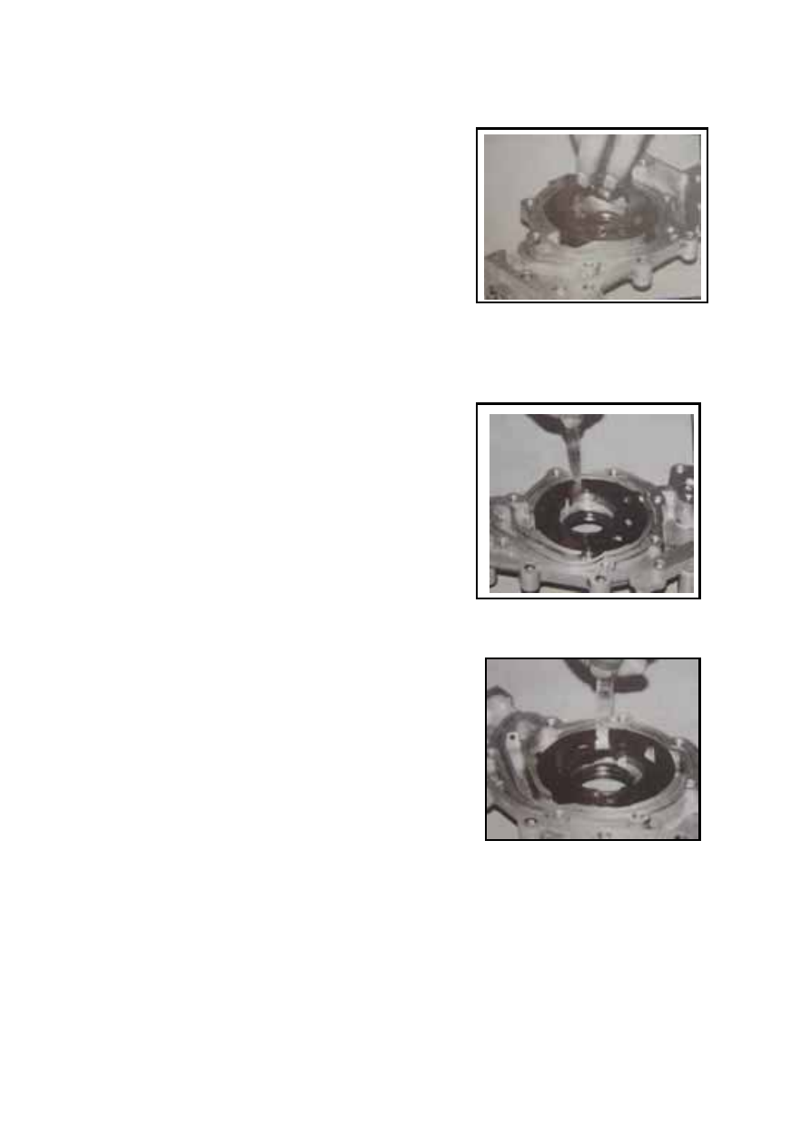
——To take out the internal and external rotors. 


——To check out the clearance between the pump 

external rotor and pump body. The oil pump 
external rotor shall have a clearance of 
0.06-0.19mm with oil pump body. 


——To check out the radial clearance between oil 

pump internal rotor and external rotor. The 
clearance between internal and external rotors 
shall be 0.05-0.18mm. 


D-7


——To check out the rotor end clearance. 

The rotor end clearance shall be 0.014-0.100mm. 


——To unscrew and take out the horizontal internal 

hexagon bolts (small ones). 

——To take out relive vale spring and relief valve 

ball. 

——To check out the spring load and free length. 


The free length is 46mm; 

The spring load is 32.8N±2N at 29mm; 

The installation length of relief valve spring is 
38.5mm.


——Bad relief vale spring, if any, has to be changed. 


D-8


Assembly: 

——To place external and internal rotors into the oil 

pump body, making sure the installation marks 
on the external and internal rotors are upward.


——To place the oil pump cover plate onto the oil 

pump, screw up the 7 bolts to 7-10N.m. 

——To install the relief valve and relief spring into 

the oil pump hole. 

——To screw the bolt into the oil pump body to 

20-25N.m.  

——To use oil to adhibit the new oil pump gasket to 

the front end of the cylinder body. 

——To mount the oil pump to the front end of the 

crankshaft, pointing to the internal hole of the 
internal rotors.


——To screw up the six installation nuts manually. 

——To check out and adjust evenness between the oil 

pump bottom and cylinder oil pan flange to the 
range of  ±0.26mm. 

— — To screw tightly the oil pump set bolts to 

8-11N.m.  

— — To spread engine lubrication oil on the 

crankshaft oil seal journal. 

——To cover the crankshaft oil seal journal with a 

thin plastic strip to prevent damages to crankshaft 
oil seal edge. 

— — To spread engine lubrication oil onto the 

crankshaft oil seal edge and use appropriate 
sleeve and crank belt wheel and belt wheel to 
screw tightly the bolts and washers to press the 
oil seal in place. 


D-9


——To remove the thing plastic strip. 


OIL FILTER AND OIL PRESSURE SENSOR 


Disassembly: 

——To demount the oil filter by rotating the filter 

counterclockwise. 

——To remove the oil pressure sensor.


Assembly: 

——To spread engine lubrication oil onto the oil filter 

gasket and screw it up to the fitting to 12-17N.m., 
or screw the oil filter manually and screw more 
3/4-1 round when the rudder gasket reaches the 
cylinder. 

——To spread Letai 243 seal glue onto the oil 

pressure sensor screw threads and screw it to the 
cylinder main oil passage to 25-29N.m. 

Oil pressure sensor screw threads are 1/4″-18NPTF. 

The supply voltage of oil pressure sensor is 6-24V. 

The alarm triggering pressure is 30±15Kpa. 


8.0-25.0N.M Fastening Torque Of 8.0-25.0N.M 

Oil Pressure Sensor 

Oil Filter 


D-10


Content   ..  15  16  17  18   ..