Chery A series. Manual - part 15
 

  Index      Chery     Chery A series - service repair manual


Search            copyright infringement  


Content   ..  13  14  15  16   ..


Chery A series. Manual - part 15


Installation 

 
Piston weights and spare piston skirts are not 
grouped, but the piston pin holes shall be 
grouped. Before assembly, check the piston 
crown marks. The marks of the four cylinders 
must be same.   

Heat the small end of the connecting rod to 
230~400℃, apply SAE50 lube or glue type of 
graphite oil, then press the piston pin into the 
small end bore of the connecting rod and the 
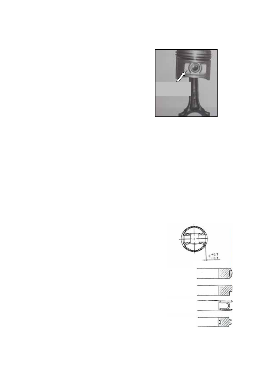
piston pin bore. One end of the piston pin can 
be 0.7mm(max)higher than the pin boss or 
lower than the pin seat, and the other end shall 
be in the pin boss. 

The forward pointing arrow on the piston 
crown and the forward pointing bump on the 
external surface of the piston pin seat shall be 
in the same direction with the “F” near the big 
end on the connecting rod body (For some 
blanks forged with the number “480”, the side 
with the number shall be upward.     

After connecting the piston, piston pin and the 
connecting rod together, print or chisel the 
cylinder number (size: 3mm) on the top of the 
piston, connecting rod body and left of the 
connecting rod cap. The printing shall not lead 
to the distortion of the junction plane. 


When installing the piston ring, the side with 
characters shall be upward and the external 
slit of the second compression ring shall be 
downward. Detailed order is as follows: (1) 
install the oil control piston ring; (2) install 
the second compression ring and (3) install 
the first compression ring. When installing the 
ring, the max. expanding must be less than 
(size of cylinder bore + 1.65mm) , otherwise 
the ring is subject to distortion or broken off. 
The opening of the two sealing strips of Steel 
belt combination oil control ring shall be 
staggered from each other by 120°while the 
one of cast iron oil ring shall be stagger from 
that of spiral bushing ring by 180°. The 
piston shall be able to rotate freely in the ring 
groove and no jamming shall exist. 


Forward 
pointing bump 


Only one side

Cast spiral oil control ring 

Steel belt combination
oil control ring 

2

nd

compression ring

First compression ring

B-37

Size of piston ring 

480# piston ring 

Paint mark (type) 

Paint mark (type) 

No paint (Standard) 

No paint (Standard) 

Purple paint (oversized by 0.29) 

Purple paint (oversized by 0.29) 

Blue paint (oversized by 0.5) 

Blue paint (oversized by 0.5) 


INSTALLATION OF THE PISTON AND 
CONNECTING ROD ASSEMBLY


Apply some motor oil in the piston, piston ring 
and cylinder, with the first and second 
compression ring staggered from the opening 
of the oil control piston ring by 120°, then 
install the piston and connecting rod assembly 
into the cylinder. The piston and connecting
rod assembly may be pushed into the cylinder 
by a hammer.   

Apply some    motor oil on the connecting-rod 
bearing shell and install the connecting rod cap 
and body. The connecting rod cap is fixed by 
two elastic dowels.   

Tighten the connecting rod bolts to the moment 
of 30-36N.m. Before installation, apply some 
motor oil on the bolt heads and threads.   

The side clearance of the big end of the 
connecting rod is 0.0092-0.268mm. 


B-38


LUBRICATION SYSTEM 

DESCRIPTION OF LUBRICATION SYSTEM …… … …… ……… … …… ………D-2 

OIL PAN …… … …… ……… … …… ……… … …… ……… … …… ……… … …D-3   

DISASSEMBLY/ASSEMBLY …… ……… … ………… ……… … ………… …D-3 


OIL FILLING …… ……… … …………………………… … ………… ……… … …D-5 

OIL STRAINER ASSEMBLY …… ……… … ………… ……… … ………… ……… D-5   

DISASSEMBLY/ASSEMBLY …… ……… … ………… ……… … ………… …D-5


OIL PUMP AND FRONT OIL SEAL ………………… … ………… ……… …D-6


DISASSEMBLY/ASSEMBLY …… ……… … ………… ……… … ………… …D-6


OIL FILTER AND OIL PRESSURE SENSOR …… ……… … ………… ……… …D-10


DISASSEMBLY/ASSEMBLY …… ……… … ………… ……… … ………… …D-10


OIL PRESSURE TESTING PARAMETER LIST …… ……… … ………… ………D-11


D-1

ENGINE LUBRICATION SYSTEM 

DESCRIPTION OF LUBRICATION SYSTEM 

——The rotor oil pump (1) at the front end of the 

crankshaft    sucks oil out of the oil pan (3) by 
oil strainer (2) and pressurizes oil, and then 
the pressurized oil will enter the full-flow oil 
filter through the auxiliary oil passage (4) at 
the left side of the cylinder(view from the 
front). A relief valve (6) is set up inside the oil 
pump to control the pressure at the main oil 
passage. The relief valve opens at 
440kpa+20kpa, and the filtered oil flow from 
the center hole in oil filter through the center 
hole of the filter terminal to the engine main 
oil passage. 


——The main oil passage lubricate the main 

bearing through holes on the cylinder block 
and lubricate the connecting-rod bearing 
through the oil passage inside the crank shaft. 


——On the side of the vent pipe of the 

connecting-rod bearing is a small oil hole 
from    where oil will eject to lubricate piston 
pin and cylinder. 


——Oil pressure sensor (8) is close to oil filter, 

connected to the main passage through an 
internal oil passage. And engine oil will be 
provided upward to the third camshaft journal 
from the upper oil passage. 


——Other camshaft journals get oil from the 

middle passage of the camshaft, whose ends 
are sealed with steel balls.


6. Oil Pump Relief Valve 

7. Oil Filter 

8. Oil Pressure Sensor 

9. Camshaft 

10. Hydraulic Jib 


1. Oil Pump Rotor Assembly 

2. Oil Strainer 

3. Oil Pan 

4. Cylinder Auxiliary Oil Passage 

5. Cylinder Main Oil Passage


D-2


Content   ..  13  14  15  16   ..