Alfa Romeo Stelvio (2022 year). Manual in english - page 3
 

  Index      Manuals     Alfa Romeo Stelvio (2022 year). Manual in english


Search            copyright infringement  


Content      ..     1      2      3      4      ..


Alfa Romeo Stelvio (2022 year). Manual in english - page 3


 GETTING TO KNOW YOUR CAR

44

humidity with unpleasant smells in the

passenger compartment.
When the state Start&Stop Evo is on

(engine off and car at a standstill), the

automatic recirculation management

may be turned off to prevent the

windows misting up, always taking air in

from outside, to reduce the probability

of the windows misting up (as the

compressor is off).

ELECTRIC WINDOWS

24)

They work with the ignition device in

the ON position and for about 3 minutes

after the ignition device has been turned

to the STOP position. When one of the

front doors is opened this operation is

disabled.

Driver side front door controls

The buttons are located on the door

panel trim. All windows can be controlled
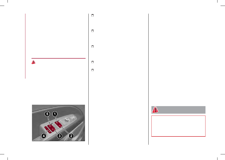
from the driver side door panel fig. 53.

53

04166V0001EM

(1): left front window opening/closing.

"Automatic continuous" operation during

window opening/closing and anti-pinch

system activated;

(2): right front window opening/closing.

"Automatic continuous" operation during

window opening/closing and anti-pinch

system activated;

(3): right rear window opening/closing;

"Automatic continuous" operation during

window opening/closing and anti-pinch

system activated;

(4): enabling/disabling of rear door

electric window controls;

(5): left rear window opening/closing;

"Automatic continuous" operation during

window opening/closing and anti-pinch

system activated.

Window opening

Push the buttons to open the desired

window.
Each button has two position steps.
Press gently (first position step) for

manual "burst" window travel, while

pressing the same button harder (second

position step) activates "continuous

automatic" operation.
If the button is pressed again, the

window will stop in the desired position.

Window closing

Lift the buttons to close the desired

window.

The window closing stage occurs

following the same logic described for

the opening stage both of the front door

windows and the rear door windows.

Window anti-pinch safety device

This safety system can recognise the

presence of any obstacle during the

window closing movement. If this

occurs, the system stops the window's

movement and reverts it, depending on

its position.
The anti-pinch safety function is

activated both during the manual and the

automatic operation of the window.

Electric window system initialisation

If power supply is interrupted, the

electric window automatic operation

must be reinitialised.
To perform the initialisation procedure,

which must be done on each door with

the doors closed, manually fully close the

window to be initialised.

WARNING

24)

Improper use of the electric windows

can be dangerous. Before and during their

operation, ensure that any passengers are

not at risk from the moving glass either

by personal objects getting caught in the

mechanism or by being hit by it directly.

-------------------------------------------------------------------------------------------------------------------------------------------------------------

45

ELECTRIC SUNROOF

(where provided)

25)

The electric sunroof comprises two

glass panels (the front one is mobile and

the rear one fixed) and is fitted with an

electrically operated sun blind.
Operation of the sunroof is only possible

with the ignition device at AVV.
The sun roof has three preset positions:

fully closed; comfort (intermediate

opening) fully open.
WARNING You cannot have the blind

closed when the roof is open.

OPENING

Press the (1) fig. 54 symbol on button

: the roof will open to the comfort

position. A second press will open it fully.
A long press of the same button will

open the roof until it is released, or if

held down, until it reaches the comfort

position. Use the button in the same way

to open the roof fully from that position.

10)

The automatic motion can be interrupted

in any position by pressing button

(1)again.
If the electric blind is closed, the roof

opening control opens it too.

54

04186S0001EM

CLOSING

From the position of complete opening
press button (1) next to the

symbol:

the roof will close completely.
A long press of the same button moves

the roof until it is released.
The automatic motion can be interrupted

in any position by pressing button

(1)again.

SWIVEL OPENING

To bring the roof into "swivel" position,
press and release button (2) fig. 54.
This type of swivel opening can be

activated irrespective of the position of

the sun roof. When starting with the roof

in closed position, pressing the button

automatically causes its swivel-opening.

If the roof is already open, pressing the

button will open it to the swivel position.
Press button (2) again during automatic

opening or closing to stop movement of

the sunroof.

SUN BLIND MOVEMENT

The front sun blind is electrically

operated.
Press the (3) fig. 54 symbol next to
symbol : to open the sun blind.
Press the (3) symbol next to symbol

:

to close the sun blind.
The automatic motion can be interrupted

in any position by pressing button

(3)again.
If the roof is open, the sun blind closing

control will also close the roof.

ANTI-PINCH DEVICE

The sunroof has an anti-pinch safety

system capable of detecting the

presence of an obstacle during the

closing movement: if this happens, the

system intervenes and the movement of

the roof is immediately reversed into

opening.

INITIALISATION PROCEDURE

Automatic operation of the sunroof

must be initialised again in case of faulty

sunroof operation.
WARNING The anti-pinch safety function

is deactivated during the initialisation

procedure.
Proceed as follows:

Set the ignition device to AVV and

start the engine;

-------------------------------------------------------------------------------------------------------------------------------------------------------------

 GETTING TO KNOW YOUR CAR

46

press button (1) next to the

symbol

to bring the roof into completely closed

position;

open the driver side door
bring the ignition device to STOP;
within 5 seconds, set the ignition

device to AVV and start the engine;

within 10 seconds hold button (1) next

to the

symbol pressed; after 10

seconds you will hear the electric motors

of the roof and blind stop in sequence;

release the button and within 5

seconds, press button (1) next to the

symbol and hold it down (until the

cycle end): the roof will automatically

perform a complete open and close cycle

including both the window and the blind

(to indicate that the initialisation has

been successful). If this does not occur,

the procedure must be restarted from

the beginning;

check that the re-initialisation

operation was successful by checking

the “one touch” function of the window

and of the blind.

WARNING

25)

When leaving the car, make sure to take

the key with you to avoid the risk of injury to

those still inside the car due to accidental

operation of the sunroof. Improper use

of the roof can be dangerous. Before and

during operation, always check that no-one

is exposed to the risk of being injured by the

moving sunroof or by objects getting caught

or hit by it.

IMPORTANT

10)

Do not open the sun roof if a roof rack

or crossbars are fitted. Do not open the sun

roof if there is snow or ice on it: you may

damage it.

BONNET

OPENING

26) 27)

Proceed as follows:

inside the passenger compartment

pull the release lever fig. 55 or fig. 56

(according to the version/market of the

vehicle);

55

04196V0001EM

56

04196V0003EM

go to the outside of the vehicle and

position yourself in front of the grille;

slightly lift the bonnet and operate the

release device from the side from the

right leftwards as shown by the arrow,
fig. 57;

57

04196V0002EM

raise the bonnet completely: the

operation is facilitated by the presence

of two gas shock absorbers which hold it

the all open position.

-------------------------------------------------------------------------------------------------------------------------------------------------------------

47

Do not tamper with the shock absorber

and accompany the bonnet while lifting

it.

CLOSING

26) 28)

To close, lower the bonnet to

approximately 40 centimetres from the

engine compartment then let it drop.

Make sure that the bonnet is completely

closed and not only fastened by the

locking device by trying to open it. If it is

not perfectly closed, do not try to press

the bonnet down but open it and repeat

the procedure.
WARNING Always check that the bonnet

is closed correctly to prevent it from

opening while the vehicle is travelling.

Since the bonnet is equipped with a

double locking system, one for each side,

you must check that it is closed on both

its side ends.

WARNING

26)

Perform these operations only when the

car is stationary.

27)

Use both hands to lift the bonnet. Before

lifting, check that the windscreen wiper

arms are not raised from the windscreen or

in operation, that the car is stationary and

that the electric parking brake is engaged.

28)

For safety reasons, the bonnet must

always be properly closed while driving.

Therefore, make sure that the bonnet

is properly closed and that the lock is

engaged. If you discover that the bonnet

is not perfectly closed while driving, stop

immediately and close the bonnet in the

correct manner.

TAILGATE

The tailgate is operated electrically,

so pay the utmost attention before

activating its movement.
Safe opening and closing of the

tailgate is guaranteed by a protection

system that can automatically stop

its movement when it encounters an

obstacle while opening or closing.
When the car is moving, tailgate

unlocking and movement are disabled.
To avoid difficulties in tight spaces, you

can set the height at which to block the

tailgate open.

Customising the tailgate opening

height

To customise the tailgate opening

position, proceed as described below:

open the tailgate;
manually move it to the position that

you want to store;

press one of the closing buttons (2)

or (3), fig. 62 for at least 5 seconds

(successful activation is indicated by the

direction indicators flashing three times).

The tailgate is now programmed to open

to the set position.
This function can be selected by acting
on the Connect system fig. 58.

58

04206V0038EM

Setting the tailgate opening height to a

preset position

(where provided)
To set the tailgate opening height to one

of the four preset positions, proceed as

follows:

activate the Main menu on the

Connect system and select the following

functions in sequence: "Settings", "Doors

and Locks" and "Electric Tailgate";

select one of the four pre-set positions

and then press the graphic button to

activate the selected position.

OPENING

WARNING A beeper always sounds while

the tailgate is in motion.

-------------------------------------------------------------------------------------------------------------------------------------------------------------

 GETTING TO KNOW YOUR CAR

48

Opening from the outside

When unlocked, you can open the tailgate

from outside the car by pressing the

electric opening button located between

the number plate lights for about one

second until you hear the unlocking click,
or by pressing the button

on the

remote control twice quickly.

59

04056V0005EM

The direction indicators will blink twice

and the internal lights will switch on when

the tailgate is opened. They switch off

automatically when the tailgate is closed.
The lights switch off automatically after

a few minutes if the tailgate is left open.

Opening from the inside

When it is locked, the tailgate can be

opened from inside the car by lifting
the button (1) fig. 60 on the driver’s door

panel trim.
WARNING You can stop the tailgate

moving by pressing the same button

again.

60

04206V0002EM

EMERGENCY OPENING FROM INSIDE

THE BOOT

There is a flap fig. 61 on the boot internal

trim, next to the tailgate lock, accessible

by folding down the rear seat backrest,

which allows access to the manual lock

opening cord.
Pull the cord to release the lock: the

tailgate can now be lifted manually.

61

04206V0014EM

CLOSING

It is possible to close the tailgate by

pressing:

the button (2) fig. 62 on the tailgate

interior lining;

the button (3) on the tailgate interior

trim, (all the doors, including the tailgate,

will be locked);

the

button on the remote

control twice quickly;

the button fig. 59 on the tailgate,

between the number plate lights.

62

04056V0055EM

WARNING It is possible to stop the

tailgate moving with any of the close

buttons.

Closing from inside

Press the button (1) fig. 60 on the plate on

the driver’s door panel and hold it down

until the operation is complete.
WARNING It is possible to stop the

tailgate moving by releasing the button.

Closing from outside

-------------------------------------------------------------------------------------------------------------------------------------------------------------

49

AUTOMATICALLY OPENING AND

CLOSING THE ELECTRICALLY

OPERATED TAILGATE IN

“HANDS-FREE” MODE

(where provided)
To operate the system in “hands-free”

mode, proceed as follows:

if the doors are locked or unlocked, the

system must recognise the electronic

key fob near the tailgate;

go to the rear of the car, in the centre

and about 20 in (50 cm) from the tailgate;

move your foot under the bumper,

simulating a kick. When you have done

this movement, withdraw your leg. To

activate the movement, both sensors

must detect your leg fig. 63.

63

04206V0015EM

If it is closed, the electrically

operated/hands-free tailgate:

unlocks and opens completely;
with another movement of the foot, it

stops;

a further movement of the foot

reverses the direction and closes the

tailgate completely, if you do not stop it

again.
If it is open, with a movement of the foot,

the electrically operated/hands-free

tailgate:

closes completely;
another movement of the foot before

it closes completely will stop it;

if the tailgate was stopped, another

movement of the foot reverses the

direction and opens it completely.
You can activate/deactivate the

automatic tailgate opening and closing

function in hands-free mode on the

Connect system by activating the Main

menu and selecting the following items in

sequence: "Settings", "Doors and Locks"

and "Automatic tailgate opening".
WARNING Before lifting the foot off the

ground, make sure that you are in stable

position. Do not touch any part of the car.

There is a risk of injury from touching, for

example, the very hot exhaust system.
WARNING To conserve the battery

charge, avoid performing this operation

repeatedly with the engine off.
WARNING To prevent accidentally

opening the tailgate when washing the

car at a car wash station or using a

high-pressure cleaner, use the Connect

system to disable the “Automatic

tailgate opening” function.

TAILGATE INITIALISATION

WARNING If the battery is disconnected

or the protection fuse blows, the tailgate

opening/closing mechanism must be

reinitialised as follows:

close all the doors and the tailgate;
press the

button on the remote

control;

press the

button on the remote

control.

INTERIOR FITTINGS

GLOVE COMPARTMENT

29)

To open the compartment proceed as

follows:

unlock the lock (where provided) by

placing the metal insert in the key into

the lock itself;

operate handle fig. 64, to open the

compartment.

-------------------------------------------------------------------------------------------------------------------------------------------------------------

 GETTING TO KNOW YOUR CAR

50

64

04246V0001EM

WARNING Do not insert objects of such

a size that the compartment cannot be

completely closed. Moreover make sure

that the compartment is completely

closed while driving.

SUN VISORS

To direct the visor laterally, detach the

visor from the interior rear-view mirror

side hook and turn it towards the side

window fig. 65.

65

04246V0002EM

FRONT ARMREST

This is located between the front seats.
There is a storage compartment inside
the armrest: operate the fig. 66 device to

access and raise the armrest.

66

04246V0004EM

CUP HOLDER / CAN HOLDER /

ASHTRAY

Two cup holder / can holder / ashtray
fig. 67 compartments are provided on the

central tunnel.

67

04246V0005EM

CIGARETTE LIGHTER

(where provided)

30) 31)

WARNING Always check that the
cigarette lighter fig. 68 is switched off.

68

04246V0015EM

POWER SOCKET

(where provided)
It is located within the front armrest

fig. 69.
It is possible to connect small battery-

powered appliances that have a

maximum power of 150W (e.g. cameras,

video cameras, tablets, razors, etc.) to

the socket.
WARNING Do not connect devices with

powers higher than 150W to the socket.

Do not damage the socket by using

unsuitable adaptors.

-------------------------------------------------------------------------------------------------------------------------------------------------------------

51

69

04026S0994EM

MOBILE PHONE COMPARTMENT

It is located on the passenger’s door

panel, in front of the door handle.

70

04246V0017EM

REAR CENTRAL ARMREST

The rear armrest is mobile and can be

stored in the backrest.

To lower it, pull on the tab located at

the top.

To re-close it, lift it until it is inserted in

its housing.

There are two cup/can holders and a
mobile phone compartment fig. 71 inside

the armrest.

71

04246V0018EM

WARNING The armrest was not designed

to support the weight of an adult

passenger or a child. Only use it to hold

drinks or small objects.

FIRE EXTINGUISHER

(where provided)
On some versions, there is a

fire extinguisher in the luggage

compartment.
For other versions/markets, the fire

extinguisher is located under the glove
compartment on passenger side fig. 72.

72

04246V0041EM

WARNING

29)

Do not travel with the storage

compartment open: it may injure the front

seat occupants in the event of an accident.

30)

The cigar lighter gets extremely hot.

Handle it carefully and make sure that

children don’t use it: risk of fire and/or burns.

31)

Do not use the ashtray as a waste paper

basket: it may catch fire in contact with

cigarette stubs.

-------------------------------------------------------------------------------------------------------------------------------------------------------------

 GETTING TO KNOW YOUR CAR

52

WIRELESS CHARGING SYSTEM

- WCPM (Wireless Charge Pad

Module)

(where provided)
The car can be equipped with the Qi®

wireless charger system (maximum

power available 15 W), located in the
housing in the front seat armrest fig. 73.
The Qi® wireless charger system is

designed to wirelessly charge your

mobile phone. Consult the manual of your

phone to check its compatibility.
Qi® is a standard interface that uses

electromagnetic induction to transmit

electrical energy to a mobile device.

The mobile phone must be designed in
accordance with the Qi® standard to be

recharged through the WCPM system.
WARNING Keys must not be placed on

the charging mat or within 15 cm from it.

This could cause excessive heat buildup

and damage to the remote control.
WARNING Placing the keys near the

Wireless charger may prevent the engine

from starting. In this case, a dedicated

message will be shown on the display of

the Connect system to alert the driver of

the need to remove the object from the

wireless charger.
WARNING Do not place the ignition key

or any other type of metal or magnetized

object (e.g. credit cards, coins, etc.) inside

the mobile phone housing.
WARNING Make sure that you place

the mobile correctly (display facing

downwards) in the special charging

location: charging may not be enabled if

it is in the wrong position.
WARNING To avoid interference with the

key search, the wireless charger system

stops charging when any door is opened.
WARNING Make sure that there are no

metal objects between the phone and the

wireless charger system during charging.

Any such objects could overheat.

73

11116V0999EM

OPERATION

The wireless charging system is

activated in automatic mode when the

driver places his mobile phone in the

housing (WCPM) (see the previous

instructions), if the latter is compatible
with the Qi® standard.
If the mobile phone is removed from the

housing during the wireless charging

phase, this will automatically be

interrupted.
The wireless charger system enables

charging when all doors are closed

properly and the engine has been

started.
Interacting with the wireless charging

system, positioning the mobile phone in

the appropriate housing, the following

messages are shown on the Connect

system display (with specific icons and

widgets), to inform the driver about the

wireless charging system status:

"

Your phone is being charged

": is

displayed when the mobile phone is

positioned correctly in the wireless

charging compartment and the system is

activated correctly;

"

Phone fully charged

": is displayed

when the phone has completed charging

its battery;

"

Object not allowed

": is displayed

when a phone that is not enabled for

wireless charging or an object that is not

permitted (e.g. the ignition key) is placed.

"

Unavailable system

": appears when

there is a malfunction in the wireless

charger system.
The driver can deactivate the display

of messages relating to the operating

status of the wireless charging system,

using the relevant Connect system menu

-------------------------------------------------------------------------------------------------------------------------------------------------------------

53

(see the description on the dedicated

supplement).

ENVIRONMENTAL PROTECTION

SYSTEMS

PETROL VERSIONS

The systems used for reducing petrol

engine emissions are: catalytic

converter, oxygen sensors, fuel

evaporation control system and GPF

particulate filter (petrol versions with

GPF only).

DIESEL VERSIONS

The systems used for reducing diesel

engine emissions are: exhaust gas

recirculation system (EGR), oxidising

catalytic converter,(DOC), selective

nitrogen oxide catalytic converter with
AdBlue® (SCR) and particulate filter

(DPF).

32)

GASOLINE PARTICULATE FILTER GPF

(Gasoline Particulate Filter) (petrol

versions with GPF only)

The Gasoline Particulate Filter is a

mechanical filter built into the exhaust

system, which physically traps carbon

particles present in the exhaust gases of

petrol engines.
Since this filter physically traps

particulate, it must be periodically

regenerated (cleaned) at regular

intervals by burning carbon particles.

The following may occur during

regeneration: more noise and/or

worsening of car handling.
These are not faults; they do not impair

normal car performance or damage the

environment. If the dedicated message

is displayed, see contents of "Warning

lights and messages" paragraph, in

chapter "Knowing the instrument panel".

DIESEL PARTICULATE FILTER (DPF)

(Diesel Particulate Filter)

The Diesel Particulate Filter is a

mechanical filter, integral to the exhaust

system, that physically traps carbon

particles present in the exhaust gases of

Diesel engines.
Since this filter physically traps

particulate, it should be periodically

regenerated (cleaned) at regular

intervals by burning carbon particles.
During the regeneration there may be

a limited increase in the engine idle

speed, fan activation, a limited increase

in fumes and high temperatures at the

exhaust.
These are not faults; they do not impair

normal car performance or damage the

environment. If the dedicated message

is displayed, see contents of "Warning

lights and messages" paragraph, in

chapter "Knowing the instrument panel".

WARNING

32)

The catalytic converter and particulate

filter (DPF) reach very high temperatures

during operation. Therefore do not park the

vehicle on flammable materials (e.g. grass,

dry leaves, pine needles, etc.): fire hazard.

-------------------------------------------------------------------------------------------------------------------------------------------------------------

This section of the handbook provides all information that is

useful for getting to know, interpreting, and using the

instrument panel correctly.

KNOWING THE INSTRUMENT PANEL

DASHBOARD AND INSTRUMENT PANEL . . . . . . . . . . . . . . . . . . . . . . . . . . . . . 56
DISPLAY . . . . . . . . . . . . . . . . . . . . . . . . . . . . . . . . . . . . . . . . . . . . . . . . . . . . . . . . . . . . . . . . . . . .61
DISPLAY DESCRIPTION . . . . . . . . . . . . . . . . . . . . . . . . . . . . . . . . . . . . . . . . . . . . . . . . . 62
WARNING LIGHTS AND MESSAGES . . . . . . . . . . . . . . . . . . . . . . . . . . . . . . . . . . . 67
EOBD SYSTEM (European On Board Diagnosis) . . . . . . . . . . . . . . . . . . . . . .90

-------------------------------------------------------------------------------------------------------------------------------------------------------------

 KNOWING THE INSTRUMENT PANEL

56

DASHBOARD AND INSTRUMENT PANEL

74

05026S0011EM

1. Rev counter 2. Digital engine oil temperature gauge with overheating warning light 3. TFT Display 4. Digital fuel level gauge (the

triangle on the left side of the symbol indicates the side of the vehicle with the fuel filler) 5. Speedometer

-------------------------------------------------------------------------------------------------------------------------------------------------------------

57

Quadrifoglio version

75

05026S0004EM

1. Rev counter 2. Digital engine oil temperature gauge with overheating warning light 3. TFT Display 4. Digital fuel level gauge (the

triangle on the left side of the symbol indicates the side of the vehicle with the fuel filler) 5. Speedometer
Apart from the instrument panel display size, there may be small differences according to the version or the end market destination

of the car.

-------------------------------------------------------------------------------------------------------------------------------------------------------------

 KNOWING THE INSTRUMENT PANEL

58

RIGHT-HAND DRIVE VERSIONS

76

05026S0085EM

1. Rev counter 2. Digital engine oil temperature gauge with overheating warning light 3. TFT Display 4. Digital fuel level gauge (the

triangle on the left side of the symbol indicates the side of the vehicle with the fuel filler) 5. Speedometer

-------------------------------------------------------------------------------------------------------------------------------------------------------------

59

Quadrifoglio version

77

05026S0086EM

1. Rev counter 2. Digital engine oil temperature gauge with overheating warning light 3. TFT Display 4. Digital fuel level gauge (the

triangle on the left side of the symbol indicates the side of the vehicle with the fuel filler) 5. Speedometer
Apart from the instrument panel display size, there may be small differences according to the version or the end market destination

of the car.

-------------------------------------------------------------------------------------------------------------------------------------------------------------

 KNOWING THE INSTRUMENT PANEL

60

 INSTRUMENT PANEL LIGHT

ADJUSTMENT (brightness sensor)

Inside the rev counter there is a

light sensor capable of detecting

environmental light conditions and

adjusting the operating mode (night/day)

and the brightness of the instrument

panel and the Connect system display.

ENGINE OIL TEMPERATURE GAUGE

The digital bar indicator monitors the

temperature of the engine oil and starts

supplying indications when the fluid

temperature reaches approximately

122°F (50°C).
Under normal usage, the digital scale

should hover around the middle of

the scale according to the working

conditions.
The

warning light switches on to signal

the excessive increase of the engine oil

temperature.
In this case, immediately stop the engine

and contact an Alfa Romeo Dealership.

FUEL LEVEL GAUGE

The bar digital gauge monitors the

amount of fuel in the tank.
The

warning light turns on, a message

is displayed and an acoustic signal is

emitted, when about 1.8 UK gal (8 litres)

of fuel are left in the tank for diesel

versions, and about 2 UK gal (9 litres)

of fuel for petrol versions). Proceeding

further, the second white notch will go

off and the last one will become red,

together with the indication "E" present
at the bottom of the tank fig. 78.
WARNING If the warning light switches

on, refuel at the earliest opportunity.
WARNING Do not travel with the fuel

tank almost empty: any gaps in fuel

supply could damage the catalytic

converter.

78

05026S0044EM

-------------------------------------------------------------------------------------------------------------------------------------------------------------


Content      ..     1      2      3      4      ..