Alfa Romeo Giulia (2022 year). Manual in english - page 12
 

  Index      Manuals     Alfa Romeo Giulia (2022 year). Manual in english


Search            copyright infringement  


Content      ..     10      11      12      13     ..


Alfa Romeo Giulia (2022 year). Manual in english - page 12


193

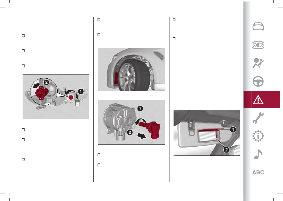
To change the bulb of these lights,

proceed as follows:

working from inside the engine

compartment fig. 206 remove the (1)
fig. 208 turning it;

release the bulb, bulb holder and

connector assembly (2) and then slide it
off the headlight body fig. 208;

remove the bulb by sliding it off the

bulb holder;

208

08026S0100EM

install the new bulb, making sure it is

correctly inserted in the bulb holder;

then insert the bulb, bulb holder and

connector assembly in the housing on

the headlight body and turn it clockwise,

making sure that it is locked correctly;

remount the lid and cover, tightening

the fixing bolts.

Fog lights

To replace the bulbs, proceed as follows:

remove the lower cover from the

wheel arch by unscrewing the fixing
screws fig. 209;

pull out the bulb-bulb holder assembly

(1) from the headlight body by turning it
anticlockwise (2)fig. 210;

209

08026S0021EM

210

08026S0101EM

remove the bulb by sliding it off the

bulb holder;

install the new bulb, making sure it is

correctly inserted in the bulb holder;

then insert the bulb and bulb holder

assembly in the housing on the headlight

body and turn it clockwise, making sure

that it is locked correctly;

refit the cover by tightening the fixing

screws.

Front light cluster with main

beam/dipped beam Xenon gas

discharge headlights

To replace the bulbs of the main beam

headlights/dipped headlights contact an

Alfa Romeo Dealership.

REPLACING AN INTERNAL BULB

Courtesy mirror light

: lift the cover (1)

fig. 211and replace the bulb 2, releasing

it from the side contacts, making sure

that it is correct blocked between the

contacts themselves.

211

08026S0008EM

Glove compartment light

: replace the

bulb in the seat fig. 212, making sure it is

locked correctly.

Direction indicators

-------------------------------------------------------------------------------------------------------------------------------------------------------------

 IN AN EMERGENCY

194

212

08026S0009EM

Boot ceiling light

: act at the point

indicated by the arrow fig. 213, remove

the ceiling light and replace the lamp,

making sure that it is correctly blocked

between the contacts.

213

08026S0010EM

Puddle light on door panel

: act at the

point indicated by the arrow fig. 214,

remove the ceiling light and replace the

lamp, making sure that it is correctly

blocked between the contacts.

214

08026S0012EM

FUSES

GENERAL INFORMATION

162) 163) 164) 165) 166) 167)

74) 75)

For fuse replacement, contact an Alfa

Romeo Dealership.
When a device does not work, check

the condition of its protection fuse: the

filament (1) must be intact.
If it is not, replace the blown fuse with

another with the same ampere rating

(same colour).
2 = intact fuse / 3 = fuse with damaged

filament.
fig. 215: MINI fuse / fig. 216: J-CASE fuse.

215

08036S0001EM

216

08036S0002EM

Fuse tongs

To replace a fuse, use the tongs housed
in the boot fusebox cover fig. 217.
Grab the pliers from the upper tabs,

press them and extract the pliers pulling

upwards.

-------------------------------------------------------------------------------------------------------------------------------------------------------------

195

217

08036S0053EM

FUSEBOX UNDER PASSENGER SIDE

FOOTBOARD

To access the fuses, proceed as follows:

lift the upper end of the footboard (1)

fig. 218 on the passenger side, pulling it to

release the 2 buttons;

remove the panel (2) fig. 218,

extracting it downward, after unscrewing

the two fixing hooks;

the fuses are freely accessible on the

control unit.

218

08036S0020EM

The number identifying the electrical

component corresponding to each fuse is

shown on the control unit cover.
After replacing the fuse, make sure that
panel (2) fig. 218 and footboard (1) are

correctly locked.

BOOT FUSEBOX

To access the fuses, lift the loading

surface and then remove the fusebox

cover fig. 219.

219

08036S0014EM

The number identifying the electrical

component corresponding to each fuse is

shown on the cover.
After replacing a fuse, make sure that

you have closed cover correctly.

WARNING

162)

For fuse replacement, contact an Alfa

Romeo Dealership.

163)

Never replace a fuse with another with

a higher amp rating; RISK OF FIRE.

164)

Before replacing a fuse, make sure

that the ignition device is at STOP and

that all devices are switched off and/or

disconnected.

165)

Contact an Alfa Romeo Dealership

if a safety system (air bags, brakes),

transmission system (engine, gearbox) or

steering system general protection fuse

blows.

166)

If a fuse blows again, contact an Alfa

Romeo Dealership.

-------------------------------------------------------------------------------------------------------------------------------------------------------------

 IN AN EMERGENCY

196

167)

If a general protective fuse (MAXI-

FUSE, MEGA-FUSE, MIDI-FUSE) blows,

contact an Alfa Romeo Dealership.

IMPORTANT

74)

Never replace a faulty fuse with metal

wires or anything else.

75)

If it is necessary to wash the engine

compartment, take care not to directly hit

the fusebox and the window wiper motors

with the water jet.

-------------------------------------------------------------------------------------------------------------------------------------------------------------

197

FUSEBOX UNDER PASSENGER SIDE FOOTBOARD

220

08036S0013EM

FUNCTION

FUSE

AMPERE

Front electric window (driver side)

F33

25

Front electric window (passenger side)

F34

25

Power supply for Connect system, Climate Control system, Alarm,

Electric door mirror folding, EOBD system, USB port

F36

15

Power Lock Device (Driver side door unlocking - where

provided)/Door unlocking, Central locking

F38

20

-------------------------------------------------------------------------------------------------------------------------------------------------------------

 IN AN EMERGENCY

198

FUNCTION

FUSE

AMPERE

Windscreen washer pump

F43

20

Rear left electric window

F47

25

Rear right electric window

F48

25

Heater rear window coil, cigar lighter

F94

15

-------------------------------------------------------------------------------------------------------------------------------------------------------------

199

LUGGAGE COMPARTMENT FUSEBOX

221

08036S0015EM

FUNCTION

FUSE

AMPERE

Tow hook module (TTM)

F1

40

Hi-Fi system

F8

30

KL15/a USB Recharge (C070)

F17

7.5

I-Drive / USB / AUX port

F21

10

KL15/a 12V Power socket (R053)

F22

20

-------------------------------------------------------------------------------------------------------------------------------------------------------------

 IN AN EMERGENCY

200

TYRE REPAIR KIT

(where provided)

DESCRIPTION

168) 169) 170) 171) 172) 173) 174) 175) 176) 177)

76)

3)

The Tyre Repair Kit is located in the boot,

inside a specific container.
To access the Tyre Repair Kit, open the

boot, lift the load platform.
The Tyre Repair Kit includes also:

a bottle (1) fig. 222 containing sealant,

provided with: filling pipe (2) and

adhesive label (3) with the words "Max.

80 km/h”, to be attached in a position

easily visible to the driver (e.g. on the

dashboard) after repairing the tyre;

222

08066S0002EM

compressor (4) complete with

pressure gauge and connectors;

an instruction leaflet, to refer to for

prompt and correct use of the Tire

Repair Kit and that must be then given

to the personnel dealing with the tyre

treated with sealant;

a pair of protective gloves;
some adaptors, for inflating different

elements.
WARNING The sealing liquid is effective

for external temperatures between

­ 40°F and +122°F (­ 40°C and +50°C). The

sealant has an expiry date.

INFLATION PROCEDURE

168) 169) 171) 172) 173) 174) 175) 176)

Proceed as follows:

engage the electric parking brake.

Insert the bottle (1) fig. 223 containing the

sealant in the proper compressor holder,

pressing down hard.
Unscrew the tyre valve cap, take out the

inflation hose (2) and tighten the ring on

the tyre valve;

223

08066S0004EM

make sure that switch (5) fig. 224 of

the compressor is in OFF position;

224

08066S0005EM

insert the plug into the socket on the

central tunnel, start the engine;

start the compressor, placing the

switch (5) fig. 224 in the ON position;

inflate the tyre to the pressure

indicated in the “Rims and Tyres”

paragraph (see “Technical data” chapter).

In order to obtain a more precise reading,

check the pressure value on pressure
gauge (6) fig. 224 with the compressor

off;

if after 15 minutes pressure is not

at least 26 psi (1.8 bar), disengage the

compressor from the valve and power

socket, then move the car forwards

approx. five wheel turns in order

to distribute the sealant inside the

tyre evenly, then repeat the inflation

operation;

-------------------------------------------------------------------------------------------------------------------------------------------------------------

201

if you still cannot obtain a pressure of

at least 26 psi (1.8 bar) within 15 minutes

from the compressor switching on, do

not drive off and contact an Alfa Romeo

Dealership;

after having driven for about 5 miles

(8 km), stop, engage the electric parking

brake and recheck the tyre pressure;

if the pressure is less than 26 psi (1.8

bar), do not go back into gear but see an

Alfa Romeo Dealership;

if a pressure value of at least 26 psi

(1.8 bar) is detected, restore the correct

pressure (with engine running and

electric parking brake), resume driving

immediately and drive with great care to

an Alfa Romeo Dealership.

SEALANT BOTTLE REPLACEMENT

WARNING Only use original cartridges

which can be purchased at an Alfa Romeo

Dealership.
Proceed as follows:

Remove the bottle (1) fig. 225 by

pressing on the release button (9);

insert the new bottle and press it

firmly downwards.

225

08066S0009EM

WARNING

168)

Punctures on the sides of the tyre may

not be repaired. Do not use the Tyre Repair

kit if the tyre was damaged as a result of

being used when underinflated.

169)

Wear the protective gloves provided

with the Tyre Repair kit.

170)

Apply the adhesive label where it can

be easily seen by the driver as a reminder

that the tyre has been treated with the Tyre

Repair Kit. Drive carefully, particularly on

bends. Do not exceed 80 km/h. Avoid sudden

acceleration or braking.

171)

You must always indicate that the tyre

was repaired using the Tyre Repair Kit. Give

the booklet to the technicians who will be

handling the tyre that was treated using the

Tyre Repair Kit.

172)

Repairs are not possible in the case

of damage to the wheel rim (bad groove

distortion causing air loss). Do not remove

foreign bodies (screws or nails) from the

tyre.

173)

Never operate the compressor for

longer than 20 consecutive minutes.

Risk of overheating. The Tyre Repair

Kit is not suitable for definitive repairs,

so the repaired tyres may only be used

temporarily.

174)

As required by current regulations,

the information on chemical substances

for the protection of human health and the

environment and on the safe use of the

sealing fluid are on the packaging label.

Compliance with the indications on the

label is an essential condition to ensure the

safety and the effectiveness of the product.

Remember to carefully read the label before

use; the user of the product is responsible

for any damages caused by improper use.

The sealing fluid has an expiry date. Replace

the bottle if the sealant has expired.

175)

If the pressure falls below 1.8 bar, do

not drive any further: the Tyre Repair Kit

cannot guarantee proper seal because the

tyre is too damaged. Contact an Alfa Romeo

Dealership.

176)

The Tyre Repair Kit provide a

temporary repair, therefore the tyre must

be examined and repaired by a specialist as

soon as possible. The sealant is suitable

for use at temperatures in the range from

−40°C to +50°C.

177)

Indicate the presence of the stationary

car in accordance with current regulations:

hazard warning lights, warning triangle, etc.

Those on board should get out of the vehicle

and wait for the wheel to be repaired away

from the threat posed by the traffic. If

parked on a slope or rough surface, chock

the wheels with wedges or other suitable

devices (for the correct procedure for

parking the car safely, refer to the "Parking"

-------------------------------------------------------------------------------------------------------------------------------------------------------------

 IN AN EMERGENCY

202

paragraph in the "Starting and driving"

chapter).

IMPORTANT

76)

In the event of a puncture caused by

foreign bodies, the kit may be used to repair

tyres showing damage on the tyre tread up

to max. 6 mm diameter.

IMPORTANT

3)

Dispose of the bottle and the sealant

liquid properly. Have them disposed of

in compliance with national and local

regulations.

RUN FLAT TYRES

(where provided)

178) 179)

"Run Flat" tyres allow you to maintain

control of the car after a puncture and to

continue driving safely for about 50 mi

(80 km) at a maximum speed of 50 mph

(80 km/h).
The reinforced tyre wall retains its shape

and supports the weight of the car in the

event of pressure loss.
Cars equipped with Run Flat tyres are

NOT provided with Tyre Repair Kits. For

repair, contact an Alfa Romeo Dealership

as soon as possible.

WARNING

178)

A pressure loss alters the driving

behaviour of the car, for example, causing

less directional stability when braking,

longer braking distances and altered

steering geometry. Therefore, adjust your

driving style to avoid sudden turns or

obstacles such as pavements and potholes.

179)

Do not exceed 60 km/h when driving

with an especially heavy trailer.

JUMP STARTING

If the battery is flat, a jump starting can

be performed using the battery and

the cables of another car, or using an

auxiliary battery. In all cases, the battery

used must have a capability equal to or a

little higher than the flat one.
Jump starting may be dangerous if

carried out incorrectly: carefully follow

the procedures described below.

77)

WARNINGS

Do not use an auxiliary battery or any

other source of external supply with

a voltage above 12V: the battery, the

starter, the alternator and the electrical

system of the car could be damaged.
Do not attempt jump starting if the

battery is frozen. The battery could

break and explode!

REMOTE BATTERY CONNECTION

POLES

To facilitate the operation, the remote

poles of the battery for the jump starting

can be found in the engine compartment:

the battery, on the other hand, is placed

in the boot.
The negative terminal (-) fig. 226 is

located next to the right bonnet catch.

226

08076S0006EM

You can access the positive terminal (+)
by remove the cover fig. 227 and lifting
the protective flap fig. 228.
The pole is shown in fig. 229.

-------------------------------------------------------------------------------------------------------------------------------------------------------------

203

227

08076S0007EM

228

08076S0002EM

229

08076S0001EM

QV version

The negative terminal (-) fig. 226 is

located next to the right bonnet catch.
The positive terminal (+) can be reached
by lifting the protective flap fig. 230 and
is shown in fig. 231.

230

08076S0004EM

231

08076S0005EM

To carry out the operation, you need to

have the correct cables to connect the

auxiliary battery to the remote poles of

the flat battery.
Usually, these cables have terminals at

the ends and are identified by different

sheath colours (red = positive, black =

negative).

STARTING WITH AUXILIARY BATTERY

180) 181) 182)

Proceed as follows:

switch off all electrical devices in the

car;

engage the parking brake, activate P

(Park) mode and then put the ignition

device in the STOP position;

should you be using the battery of

another car, park the other car within

the range of the cables used for the

connection, operate the parking brake

and ensure that its ignition is off.
WARNING If the auxiliary battery is

installed on another car, check that there

is no accidental contact of metal parts

between the two cars, since an earth

connection may result, with the risk of

serious injury to any people who may be

nearby.
WARNING If the procedure below is

carried out incorrectly, it can cause

severe injury to people or damage the

recharging system of one or both cars.

Carefully follow the instructions given

below.

Cable connection

78)

Proceed as follows to carry out a jump

starting:

-------------------------------------------------------------------------------------------------------------------------------------------------------------

 IN AN EMERGENCY

204

connect a terminal on the end of the

positive cable from the remote positive

pole (+) of the car with flat battery;

connect the terminal on the opposite

end of the positive (+) cable to the

positive (+) pole of the auxiliary battery;

connect a negative cable end terminal

to the negative (-) pole of the auxiliary

battery;

connect the terminal on the opposite

end of the negative (-) cable to the earth

point (-) on the car with the battery flat;

start the engine of the car with an

auxiliary battery, let it run for some

minutes at idle and then start the engine

of the car with flat battery.
In case a portable battery is used, before

starting the car, wait a few seconds after

completing the connection.

Cable disconnection

Once the engine is started, remove the

connection cables in reverse sequence,

as shown below:

disconnect the negative cable end

terminal (-) from the earth point (-) of the

car with flat battery;

disconnect the terminal on the

opposite end of the negative cable from

the negative (-) pole of the auxiliary

battery;

disconnect the terminal on the

opposite end of the positive (+) cable

from the positive (+) pole of the auxiliary

battery;

disconnect the terminal on the end

of the positive cable from the remote

positive pole (+) of the car with flat

battery.

WARNING

180)

Do not get too close to the radiator

cooling fan: the electric fan may start;

danger of injury. Scarves, ties and other

loose clothing might be pulled by moving

parts.

181)

Remove any metal objects (e.g. rings,

watches, bracelets), that might cause an

accidental electrical contact and cause

serious injury.

182)

The batteries contain acid that can

burn skin or eyes. Batteries produce

hydrogen, which is easily flammable and

explosive. Thus keep away flames or

devices which may cause sparks.

IMPORTANT

77)

Never use a fast battery charger to

start the engine as this could damage the

electronic systems, particularly the engine

ignition and fuel supply control units.

78)

Do not connect the cable to the negative

terminal (–) of the flat battery. The following

spark could lead to battery explosion and

cause serious harm. Only use the specific

earth point; do not use any other exposed

metallic part.

FUEL CUT-OFF SYSTEM

DESCRIPTION

The vehicle is equipped with a system

that cuts off the fuel supply in the event

of an impact, causing the engine to stop.
This safety device is controlled by the

ORC control unit, which manages all the

occupant protection systems. Depending

on the type and violence of the impact,

this control unit determines whether or

not to activate the airbags and the front

seatbelt pretensioners and whether or

not to immediately interrupt the current

from the batteries to the supply pumps

and to the devices that make the engine

operate. The power from the battery is

interrupted by "skipping" the pyrotechnic

fuse placed on the fusebox next to the

positive pole of the battery.
When the fuse is "skipped", only some

services, necessary for the safety of the

vehicle (e.g.: door locks, anti-theft device,

etc.), remain powered.
WARNING After the impact, carefully

check the vehicle for fuel leaks, for

instance in the engine compartment,

under the vehicle or near the tank area.
WARNING Contact an Alfa Romeo

Dealership to have the system checked.

-------------------------------------------------------------------------------------------------------------------------------------------------------------

205

ENGINE OVERHEATING

WARNING An overheated cooling

system can damage the car. In the case

of overheating, pull over and stop the

car. Keep the engine at idling with air

conditioning off until the temperature

decreases. If temperature does not

decrease, contact an Alfa Romeo

Dealership as soon as possible.
WARNING Coolant (antifreeze) exiting

from the engine or vapour exiting from

the radiator can cause serious burns. If

vapour is seen or heard coming from the

engine compartment, do not open the

bonnet until the radiator has had enough

time to cool down. Never try to remove

the cap when the radiator is hot.

AUTOMATIC TRANSMISSION

GEAR LEVER RELEASE

To release the automatic transmission

lever, contact an Alfa Romeo Dealership.

TOWING A BROKEN-DOWN CAR

This paragraph describes the conditions

and methods to transport and tow a

broken-down car with a breakdown truck.
The assistance car operators must be

informed about the minimum ground

clearance of the car in order to avoid

contact between the ends of the bumper

with the tow truck equipment.
The front and rear attachment corners

of the car, to be taken into consideration

when loading the car on the roadside
assistance vehicle are shown in fig. 232.

232

08126S0001EM

RWD versions

A

: 12.880°

B

: 17.105°

AWD versions

A

: 15.160°

B:

18.400°

QV versions

A

: 12.045°

B

: 11.830°

REAR-WHEEL DRIVE (RWD) VERSIONS

It is recommended to tow the car with

all four wheels lifted from the ground on

the platform of a roadside assistance

vehicle.
If a tow truck with platform is not

available, the car must be towed with

the rear wheels LIFTED from the ground

(using a trailer or special equipment

allowing lifting of the rear wheels).

ALL-WHEEL DRIVE (AWD) VERSIONS

It is recommended to tow the car with

all four wheels lifted from the ground on

the platform of a roadside assistance

vehicle.
WARNING Avoid lifting the front (or

rear) wheels only, using a trailer or car

that allows lifting the wheels of one axle

only. Lifting the front (or rear) wheels

only while towing might damage the

transmission or the transfer unit.

WARNINGS

If a car is towed without complying

with the above requirements, the

transmission and/or the transfer unit

might be seriously damaged (on AWD

-------------------------------------------------------------------------------------------------------------------------------------------------------------

 IN AN EMERGENCY

206

versions). Damage due to incorrect

towing is not covered by warranty.
The car should be transported with all

four wheels lifted from the ground on the

platform of a roadside assistance car.

Avoid towing with only the front (or rear)

wheels lifted. When towing with only the

front (or rear) wheels lifted, in addition to

damaging the body, it could damage the

gearbox.
To carry out the operation, the

assistance car must be equipped with

an appropriate movement/lifting

equipment to avoid damaging the car.

For loading on the towing car, attach the

tow equipment to the main structural

components of the car and not to the

bumpers or other related brackets.
Comply with the regulations regarding

assistance and car towing in force in each

country.
When securing the car to a tow truck, do

not attach to front or rear suspension

components. Damage to your car may

result from improper towing.

TOWING THE CAR

183) 184) 185)

In order to be able to tow the car, which

has been in an accident or has broken

down, on the road surface and only for

short distances, a tow ring is provided

in the tools container inside the luggage

compartment.
Proceed as follows to use the tow hook:

release the cap fig. 233 on the front or

rear bumper (where provided) fig. 234,

pressing on the upper part;

233

08136S0001EM

234

08136S0003EM

take the tow hook from its housing in

the boot and carefully clean the threaded

housing on the vehicle before using it;

tighten the vehicle's tow hook in its

place for about 11 turns.
WARNING The largest work angle of

the cable to fix on the tow ring must not
exceed 15°, as shown in fig. 235.

235

08136S0002EM

-------------------------------------------------------------------------------------------------------------------------------------------------------------

207

WARNING

183)

Move the ignition device to ON and

then to STOP, without opening the door.

184)

The brake servo and the

electromechanical power steering will not

work while the vehicle is being towed. You

will therefore need to apply more force on

the brake pedal and steering wheel. Do not

use flexible ropes when towing, and avoid

jerky movements. While towing, make sure

that the trailer hitch does not damage any

components it is touching. When towing the

car, you must comply with all specific traffic

regulations and adopt an appropriate

driving behaviour. Do not start the engine

while towing the car. Before tightening the

ring, clean the threaded housing thoroughly.

Make sure that the ring is fully screwed into

the housing before towing the car.

185)

The front and rear tow hooks should

be used only for emergencies on the road.

You are allowed to tow the vehicle for short

distances using an appropriate device in

accordance with the highway code (a rigid

bar), to move the vehicle on the road in

readiness for towing or transport via a

breakdown vehicle. Tow hooks MUST NOT

be used to tow vehicles off the road or

where there are obstacles and/or for towing

operations using cables or other non-rigid

devices. In compliance with the above

conditions, towing must take place with the

two vehicles (one towing, the other towed)

aligned as much as possible along the same

centre line.

-------------------------------------------------------------------------------------------------------------------------------------------------------------

Proper maintenance allows car performance to be maintained

over time, operating costs to be contained, and safety system

performance to be safeguarded. This chapter explains how.

MAINTENANCE AND CARE

SCHEDULED SERVICING . . . . . . . . . . . . . . . . . . . . . . . . . . . . . . . . . . . . . . . . . . . . . . . 210
ENGINE COMPARTMENT . . . . . . . . . . . . . . . . . . . . . . . . . . . . . . . . . . . . . . . . . . . . . . .220
RECHARGING THE BATTERY . . . . . . . . . . . . . . . . . . . . . . . . . . . . . . . . . . . . . . . . . . 227
SERVICING PROCEDURES . . . . . . . . . . . . . . . . . . . . . . . . . . . . . . . . . . . . . . . . . . . . .229
LIFTING THE CAR . . . . . . . . . . . . . . . . . . . . . . . . . . . . . . . . . . . . . . . . . . . . . . . . . . . . . . . .233
WHEELS AND TYRES . . . . . . . . . . . . . . . . . . . . . . . . . . . . . . . . . . . . . . . . . . . . . . . . . . .233
PROLONGED CAR INACTIVITY . . . . . . . . . . . . . . . . . . . . . . . . . . . . . . . . . . . . . . . .234
BODYWORK . . . . . . . . . . . . . . . . . . . . . . . . . . . . . . . . . . . . . . . . . . . . . . . . . . . . . . . . . . . . . .235
INTERIOR . . . . . . . . . . . . . . . . . . . . . . . . . . . . . . . . . . . . . . . . . . . . . . . . . . . . . . . . . . . . . . . . . 237

-------------------------------------------------------------------------------------------------------------------------------------------------------------


Content      ..     10      11      12      13     ..