RAM ProMaster City (2022 year). Manual in english - page 1
 

  Index      Manuals     RAM ProMaster City (2022 year). Manual in english


Search            copyright infringement  


Content      ..      1       2         ..


RAM ProMaster City (2022 year). Manual in english - page 1


8  

SYMBOL GLOSSARY

Some car components have colored labels with symbols indicating 

precautions to be observed when using this component. It is important to 

follow all warnings when operating your vehicle. See below for the definition of 

each symbol  

Ú

page 44.

NOTE:

Warning and Indicator lights are different based upon equipment options and 

current vehicle status. Some telltales are optional and may not appear.

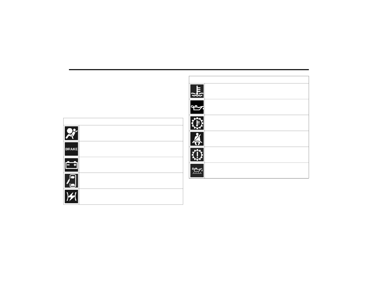
Red Warning Lights

Air Bag Warning Light


Ú

page 44

Brake Warning Light


Ú

page 45

Battery Charge Warning Light


Ú

page 45

Door Open Warning Light


Ú

page 45

Electronic Throttle Control (ETC) Warning Light


Ú

page 46

Engine Coolant Temperature Warning Light


Ú

page 46

Oil Pressure Warning Light


Ú

page 46

Transmission Temperature Warning Light


Ú

page 46

Seat Belt Reminder Warning Light


Ú

page 46

Transmission Fault Warning Light


Ú

page 47

Engine Oil Level Warning Light


Ú

page 47

Red Warning Lights

-------------------------------------------------------------------------------------------------------------------------------------------------------------

9

Yellow Warning Lights

Anti-Lock Brake System (ABS) Warning Light


Ú

page 47

Low Fuel Warning Light


Ú

page 47

Generic Warning Light


Ú

page 47

Tire Pressure Monitoring System (TPMS) Warning Light


Ú

page 47

Vehicle Security Warning Light


Ú

page 48

Engine Check/Malfunction Indicator Warning Light (MIL)


Ú

page 48

Electronic Stability Control (ESC) Warning Light


Ú

page 49

Electronic Stability Control (ESC) OFF Warning Light


Ú

page 49

Green Indicator Lights

Turn Signal Indicator Lights


Ú

page 49

Parking/Headlights On Indicator Light


Ú

page 49

Front Fog Indicator Light


Ú

page 49

Cruise Control Indicator Light


Ú

page 50

Blue Indicator Lights

High Beam Indicator Light


Ú

page 50

White Indicator Lights  

Speed Warning Indicator Light


Ú

page 50

1

-------------------------------------------------------------------------------------------------------------------------------------------------------------

10  

GETTING TO KNOW YOUR VEHICLE

KEYS 

K

EY

 F

OB

Your vehicle uses a key start ignition system which 

supports Remote Keyless Entry (RKE). The key fob 

allows you to lock or unlock the doors from 

distances up to approximately 66 ft (20 m). The 

key fob does not need to be pointed at the vehicle 

to activate the system. The key fob also contains 

an integrated mechanical key, which can be 

accessed by pushing the mechanical key release 

button.

NOTE:

The key fob may not be able to be detected by the 

vehicle if it is located next to a mobile phone, 

laptop or other electronic device; these devices 

may block the key fob’s wireless signal  

Ú

page 245.

Key Fob With Integrated Mechanical Key

To Lock/Unlock The Doors

Push and release the unlock button to unlock all 

doors (on passenger vehicles and U.S. cargo 

vehicles) or unlock the front two doors (Canada 

cargo vehicles). To lock the doors, push and 

release the lock button once. The doors can also 

be locked and unlocked manually by using the 

mechanical key.
When the doors are unlocked, the turn signals will 

flash. When the doors are locked, the turn signals 

will flash and the horn will chirp (if activated 

through the Uconnect Settings  

Ú

page 79). If a 

door is open when the lock button is pushed, the 

turn signal lights will flash at an increased rate to 

indicate that a door is still open.

Replacing The Battery In The Key Fob

The recommended replacement battery is 

CR2032.

1 — Mechanical Key Release Button
2 — Driver/Passenger Unlock Button
3 — Lock Button
4 — Cargo Lock/Unlock Button

-------------------------------------------------------------------------------------------------------------------------------------------------------------

GETTING TO KNOW YOUR VEHICLE

11

NOTE:

Customers are recommended to use a battery 

obtained from Mopar®. Aftermarket coin 

battery dimensions may not meet the original 

OEM coin battery dimensions.

Perchlorate Material – special handling may 

apply. See 

www.dtsc.ca.gov/hazard

-

ouswaste/perchlorate

.

1. Push the mechanical key release button and 

release the mechanical key to access the 

battery case screw located on the side of the 

key fob.

2. Rotate the screw located on the side of the key 

fob using a small screwdriver.

Key Fob Screw Location

3. Take out the battery case. Remove and 

replace the battery observing its polarity.

4. Refit the battery case inside the key fob and 

turn the screw to lock it into place.

Programming And Requesting Additional 

Key Fobs  

Programming the key fob may be performed by an 

authorized dealer.

NOTE:

Once a key fob is programmed to a vehicle, it 

cannot be repurposed and reprogrammed to 

another vehicle.

Only key fobs that are programmed to the 

vehicle electronics can be used to start and 

operate the vehicle. Once a key fob is 

programmed to a vehicle, it cannot be 

programmed to any other vehicle.

Duplication of keys may be performed at an 

authorized dealer. The VIN is required for 

authorized dealer replacement of keys.

NOTE:

When having the Sentry Key Immobilizer system 

serviced, bring all vehicle keys with you to an 

authorized dealer.

Keys must be ordered to the correct key cut to 

match the vehicle locks.

WARNING!

The integrated key fob contains a coin cell 

battery. Do not ingest the battery; there is a 

chemical burn hazard. If the coin cell battery is 

swallowed, it can cause severe internal burns 

in just two hours and can lead to death.

If you think a battery may have been swal

-

lowed or placed inside any part of the body, 

seek immediate medical attention.

Keep new and used batteries away from chil

-

dren. If the battery compartment does not 

close securely, stop using the product and 

keep it away from children.

WARNING!

Always remove the key fobs from the vehicle 

and lock all doors when leaving the vehicle 

unattended.

Always remember to place the ignition in the 

OFF position.

2

-------------------------------------------------------------------------------------------------------------------------------------------------------------

12

GETTING TO KNOW YOUR VEHICLE


SENTRY KEY  

The Sentry Key Immobilizer system prevents 

unauthorized vehicle operation by disabling the 

engine. The system does not need to be armed or 

activated. Operation is automatic, regardless of 

whether the vehicle is locked or unlocked.
The system uses ignition keys which have an 

embedded electronic chip (transponder) to 

prevent unauthorized vehicle operation. Therefore, 

only keys that are programmed to the vehicle can 

be used to start and operate the vehicle.
If the Vehicle Security Light is on after the key is 

placed in the MAR (ACC/ON/RUN) position, it 

indicates that there is a problem with the 

electronics.

All of the keys provided with your new vehicle have 

been programmed to the vehicle electronics.

NOTE:

A key which has not been programmed is also 

considered an invalid key, even if it is cut to fit the 

ignition switch lock cylinder for that vehicle  

Ú

page 245.

IGNITION SWITCH    

1. Place the gear selector in PARK.
2. Rotate the key to the STOP (OFF/LOCK) 

position.

3. Remove the key from the ignition switch lock 

cylinder.

Ignition Switch Positions

CAUTION!

The Sentry Key Immobilizer system is not 

compatible with some aftermarket Remote 

Starting systems. Use of these systems may 

result in vehicle starting problems and loss of 

security protection.

1 — AVV (START)
2 — MAR (ACC/ON/RUN)
3 — STOP (OFF/LOCK)

WARNING!

Before exiting a vehicle, always shift the trans

-

mission into PARK, apply the parking brake, and 

remove the key fob from the vehicle. When 

leaving the vehicle, always lock your vehicle. In 

case you switch off the vehicle and the transmis

-

sion is not in PARK, a warning message will 

appear on the cluster which indicates you to shift 

the transmission into PARK and then you can 

remove the key within 15 seconds. If 15 seconds 

expire, you have to rotate the key from the STOP 

(OFF/LOCK) position to the MAR (ACC/ON/RUN) 

position and come back to the STOP (OFF/LOCK) 

position in order to remove the key.

Never leave children alone in a vehicle, or with 

access to an unlocked vehicle. Allowing chil

-

dren to be in a vehicle unattended is dangerous 

for a number of reasons. A child or others could 

be seriously or fatally injured. Children should 

be warned not to touch the parking brake, 

brake pedal or the gear selector.

Do not leave the key fob in or near the vehicle, 

or in a location accessible to children. A child 

could operate power windows, other controls, 

or move the vehicle.

Do not leave children or animals inside parked 

vehicles in hot weather. Interior heat buildup 

may cause serious injury or death.

-------------------------------------------------------------------------------------------------------------------------------------------------------------

GETTING TO KNOW YOUR VEHICLE

13

NOTE:

When opening the driver’s door with the key in the 

ignition and the ignition placed in the STOP (OFF/

LOCK) position, a chime will sound to remind you to 

remove the key.

DOORS 

P

OWER

 D

OOR

 L

OCKS


Door Lock/Unlock Switch

The doors can be locked or unlocked from inside 

the vehicle by using the door lock/unlock switch.

To lock the doors, push down on the switch.

To unlock the doors, pull up on the switch.

A

UTO

 U

NLOCK

 D

OORS

This feature unlocks both front doors (on Canada 

cargo vehicles), or all doors (on passenger and U.S. 

cargo vehicles) when the driver door is opened.

NOTE:

If the front passenger door, or the rear or side door 

is opened, only the rear or side door is unlocked.

S

LIDING

 S

IDE

 D

OOR

On cargo versions, the sliding side door is fitted 

with a spring-loaded latch that stops the door from 

opening any farther. To lock the door in place, 

simply push the door as far as it will go; to release 

it, pull forward firmly.

Opening And Closing From Outside The 

Vehicle

Opening/Unlocking With A Key Fob In the 

Passenger Vehicle And U.S. Cargo Vehicle — 

If Equipped
Push and release the unlock button on the key fob 

to unlock all doors. Push and release the cargo 

unlock button on the key fob to unlock only the rear 

cargo doors. To open one of the sliding side doors, 

pull the handle out from the bottom, then slide the 

door towards the rear of the vehicle until it locks 

into place and cannot go any farther. The turn 

signal lights will flash to acknowledge the unlock 

signal.
Opening/Unlocking With A Key Fob In the 

Canadian Cargo Vehicle — If Equipped
Push and release the unlock button on the key fob 

to unlock the front two doors. Push and release the 

cargo unlock button on the key fob once to unlock 

the passenger/cargo area (side lateral sliding 

doors and rear doors). The turn signal lights will 

flash to acknowledge the unlock signal.
Unlocking With The Mechanical Key In Passenger 

Vehicle
Push the mechanical key release button to expose 

the mechanical key, insert the key into the driver 

door exterior lock cylinder and turn the key 

counterclockwise to unlock all doors.
Unlocking With The Mechanical Key In Cargo 

Vehicle
Push the mechanical key release button to expose 

the mechanical key and insert the key into the 

driver door exterior lock cylinder and turn the key 

counterclockwise to unlock the front doors. Insert 

the key into the rear door exterior lock cylinder and 

turn the key counterclockwise to unlock the rear 

doors.

CAUTION!

An unlocked vehicle is an invitation. Always 

remove the key from the ignition and lock all the 

doors when leaving the vehicle unattended.

2

-------------------------------------------------------------------------------------------------------------------------------------------------------------

14

GETTING TO KNOW YOUR VEHICLE


Closing/Locking With A Key Fob
Push and release the lock button on the key fob to 

lock all doors, including the cargo area (side lateral 

sliding doors and rear doors). The turn signal lights 

will flash to acknowledge the lock signal.
Horn activation settings after a key fob lock 

command can be adjusted manually through the 

Uconnect system  

Ú

page 79.

Locking With The Mechanical Key In Passenger 

Vehicle
Push the mechanical key release button to expose 

the mechanical key, insert the key into the driver 

door exterior lock cylinder and turn the key 

clockwise to lock all doors.
Locking With The Mechanical Key In Cargo Vehicle
Push the mechanical key release button to expose 

the mechanical key, insert the key into the driver 

door exterior lock cylinder and turn the key 

clockwise to lock the front doors. Insert the key into 

the rear door exterior lock cylinder and turn the key 

clockwise to lock the rear doors.
Closing And Locking From Outside
Grab the side door handle and push towards the 

front of the vehicle. Once the side door is secured 

in the full closed position, use one of the prior 

locking methods to lock the sliding side doors.

Opening And Closing From The Inside

Opening:
Pull the interior door handle to unlock the door, 

then pull the handle and slide the door towards the 

rear of the vehicle until it can go no farther.
Closing:
Pull the interior door handle to release the door 

and then push it towards the front of the vehicle.

Key Emergency Lock (KEL) Device

The sliding side doors are provided with a device 

for locking all the doors using an emergency lock in 

case of a power fault. The device is located on the 

rear of the sliding door.
The device can be engaged with the sliding side 

doors open in one of the following positions:

KEL Device not engaged (doors unlocked)

KEL Device engaged (insert the ignition key 

blade into the lock and rotate clockwise), doors 

locked

Key Emergency Lock Device

The device is released and the doors can be 

opened as follows:
If the power is restored:

By remote control.

Opening a front door by inserting the key into 

the key cylinder.

If the power is not restored:

Opening the driver side door by mechanical key 

and the other doors (passenger's side and 

sliding side door) by pulling the inner handle.

If the child lock was engaged and the previously 

described locking procedure was carried out, 

operating the internal handle will not open the door 

but will only realign the door lock knob. To open the 

door, the outside handle must be pulled. The door 

lock/unlock button is not disabled by the 

engagement of the emergency lock.

-------------------------------------------------------------------------------------------------------------------------------------------------------------

GETTING TO KNOW YOUR VEHICLE

15

D

OUBLE

 R

EAR

 S

WING

 D

OORS

The rear double swing doors are fitted through a 

fastening system which stops them when they 

reach an opening angle of approximately 90 

degrees.

Rear Door Check Strap Location

To open them wider to an angle of 180 degrees, 

push the locking device (one on each side) and 

simultaneously open the doors. The rear door 

check strap will automatically re-engage when the 

door is closed.
Using the key fob, you can do the following:

For cargo versions with swing door/cargo doors: 

centrally unlock the load compartment (sliding 

side doors + rear swing doors), centrally lock all 

the doors.

For versions with swing door: local unlocking/

locking.

Opening/Closing The First Swing Door 

From The Outside

To open the door, turn the key in the lock or push 

the cargo unlock button on the key fob and then 

pull the exterior handle to the left. To close the 

door, turn the key in the lock or push the lock 

button on the key fob.

Emergency Opening Of The First Swing 

Door From The Inside

From inside the vehicle, use the interior door 

release mechanism located on the left rear trim 

panel.

Opening The Second Swing Door

After having opened the first door, pull the handle 

located on the door face toward the rear of the 

vehicle.

C

HILD

-P

ROTECTION

 D

OOR

 L

OCK


S

YSTEM

This system prevents the sliding side doors from 

being opened from the inside. The child locks are 

located on the rear of the sliding side doors.
The child locks can only be engaged/disengaged 

with the sliding side door open.

Child Lock System

To Engage Or Disengage The Child-Protection Door 

Lock System
1. Open the rear door.
2. Insert the tip of the mechanical key into the 

lock and rotate to the lock or unlock position.

3. Repeat steps 1 and 2 for the opposite rear 

door.

The device remains engaged even if the doors are 

unlocked remotely. This system prevents the 

sliding side doors from being opened from the 

inside.

WARNING!

Avoid trapping anyone in a vehicle in a collision. 

Remember that the rear doors can only be 

opened from the outside when the 

Child-Protection locks are engaged (locked).

2

-------------------------------------------------------------------------------------------------------------------------------------------------------------

16

GETTING TO KNOW YOUR VEHICLE


NOTE:

For emergency exit from the rear seats when the 

Child-Protection Door Lock system is engaged, 

manually raise the door lock knob to the unlocked 

position, roll down the window, and open the door 

using the outside door handle.

STEERING WHEEL

T

ILT

/T

ELESCOPING

 S

TEERING

 C

OLUMN


This feature allows you to tilt the steering column 

upward or downward. It also allows you to lengthen 

or shorten the steering column. The steering 

column control is located on the steering column, 

below the turn signal lever.

Steering Column Control

To unlock the steering column, push the steering 

column control downward. To tilt the steering 

column, move the steering wheel upward or 

downward as desired. To lengthen or shorten the 

steering column, pull the steering wheel outward 

or push it inward as desired. To lock the steering 

column in position, pull the steering column 

control up until fully engaged.

SEATS    

Seats are a part of the Occupant Restraint system 

of the vehicle.

M

ANUAL

 A

DJUSTMENT

 (F

RONT

 S

EATS

)

The front driver and passenger seats can be 

adjusted forward and rearward, and (if equipped), 

may be reclined and the height and lumbar can be 

adjusted. The forward/rearward adjustment bar is 

located at the front of the seat, near the floor. 

Height, lumbar and recline adjustment controls are 

located on the outboard side of the seat.

Manual Front Seat Adjustments

WARNING!

Do not adjust the steering column while driving. 

Adjusting the steering column while driving or driving 

with the steering column unlocked, could cause the 

driver to lose control of the vehicle. Failure to follow 

this warning may result in serious injury or death.

WARNING!

It is dangerous to ride in a cargo area, inside 

or outside of a vehicle. In a collision, people 

riding in these areas are more likely to be seri

-

ously injured or killed.

Do not allow people to ride in any area of your 

vehicle that is not equipped with seats and seat 

belts. In a collision, people riding in these areas 

are more likely to be seriously injured or killed.

Be sure everyone in your vehicle is in a seat 

and using a seat belt properly.

1 — Forward/Rearward Adjustment Bar
2 — Height Adjustment Lever
3 — Recliner Adjustment Knob
4 — Lumbar Adjustment Knob

-------------------------------------------------------------------------------------------------------------------------------------------------------------

GETTING TO KNOW YOUR VEHICLE

17

Forward And Rearward Adjustment

The adjustment bar is at the front of the seat, near 

the floor. Pull the bar upward to move the seat 

forward or rearward. Release the bar once the seat 

is in the desired position. Then, using body 

pressure, move forward and rearward on the seat 

to be sure that the seat adjusters have latched.

Height Adjustment — If Equipped

The height adjustment lever is located on the 

center outboard side of the seat. Lift up or push 

down on the front lever to adjust the front of the 

seat up or down.

Recliner Adjustment

The recliner knob is on the rear outboard side of 

the seat. To recline the seatback, rotate the knob 

rearward without leaning back. To return the 

seatback to its normal upright position, lean 

forward, rotate the knob forward until the seatback 

is in the upright position.

Lumbar Support — If Equipped

This feature allows you to increase or decrease the 

amount of lumbar support. The lumbar adjustment 

knob is located on the rear upper outboard side of 

the seatback. Rotate the knob forward to increase 

and rearward to decrease the desired amount of 

lumbar support.

F

OLDING

 R

EAR

 S

EAT

 — I

F

 E

QUIPPED

To provide additional storage area, each rear seat 

can be folded flat to allow for extended cargo 

space.
1. Locate the release lever (upper outboard side 

of seat), and lift it upward until the seatback 

releases.

Seatback Release Lever Locations

2. Slowly fold down the seatback.
3. Pull forward on the lower release lever located 

on the lower outboard side of seat and lift the 

seat for extended cargo space.

WARNING!

Adjusting a seat while driving may be 

dangerous. Moving a seat while driving could 

result in loss of control which could cause a 

collision and serious injury or death.

Seats should be adjusted before fastening the 

seat belts and while the vehicle is parked. 

Serious injury or death could result from a 

poorly adjusted seat belt.

WARNING!

Adjusting a seat while the vehicle is moving is 

dangerous. The sudden movement of the seat 

could cause you to lose control. The seat belt 

might not be adjusted properly and you could 

be injured. Adjust the seat only while the 

vehicle is parked.

Do not ride with the seatback reclined so that 

the shoulder belt is no longer resting against 

your chest. In a collision you could slide under 

the seat belt and be seriously or even fatally 

injured. Use the recliner only when the vehicle 

is parked.

2

-------------------------------------------------------------------------------------------------------------------------------------------------------------

18

GETTING TO KNOW YOUR VEHICLE


Seat Release Lever

Extended Cargo Space

4. Reverse order for original setting.

H

EATED

 S

EATS

 — I

F

 E

QUIPPED

The controls for the front heated seats 

are located on the lower outboard side 

of the seat.

Heated Seat Control Button

Push the switch once to turn on the heated seats. 

The LED on the switch illuminates when the heated 

seat is on. Push the switch a second time to shut 

the heating elements off.

NOTE:

This feature is only available with the ignition 

key in MAR (ACC/ON/RUN) position.

Once a heat setting is selected, heat will be felt 

within two to five minutes.

WARNING!

Persons who are unable to feel pain to the 

skin because of advanced age, chronic illness, 

diabetes, spinal cord injury, medication, 

alcohol use, exhaustion or other physical 

condition must exercise care when using the 

seat heater. It may cause burns even at low 

temperatures, especially if used for long 

periods of time.

Do not place anything on the seat or seatback 

that insulates against heat, such as a blanket 

or cushion. This may cause the seat heater to 

overheat. Sitting in a seat that has been over

-

heated could cause serious burns due to the 

increased surface temperature of the seat.

-------------------------------------------------------------------------------------------------------------------------------------------------------------

GETTING TO KNOW YOUR VEHICLE

19

H

EAD

 R

ESTRAINTS


Head restraints are designed to reduce the risk of 

injury by restricting head movement in the event of 

a rear impact. Head restraints should be adjusted 

so that the top of the head restraint is located 

above the top of your ear.

Front Adjustment

To raise the head restraint, pull upward on the 

head restraint. To lower the head restraint, push 

the adjustment button, located on the base of the 

head restraint, and push downward on the head 

restraint.

Front Head Restraint

Rear Adjustment — If Equipped

The outboard and center head restraints are 

adjustable and removable. To raise the head 

restraint, push and hold the adjustment button, 

located on the base of the head restraint and pull 

upward on the head restraint. To lower the head 

restraint, push and hold the adjustment button, 

and push downward on the head restraint till the 

desired height is reached.

Outboard Head Restraint

WARNING!

All occupants, including the driver, should not 

operate a vehicle or sit in a vehicle’s seat until 

the head restraints are placed in their proper 

positions in order to minimize the risk of neck 

injury in the event of a crash.

Head restraints should never be adjusted 

while the vehicle is in motion. Driving a vehicle 

with the head restraints improperly adjusted 

or removed could cause serious injury or 

death in the event of a collision.

1 — Release Button
2 — Adjustment Button

WARNING!

ALL the head restraints MUST be reinstalled in 

the vehicle to properly protect the occupants. 

Follow the reinstallation instructions above prior 

to operating the vehicle or occupying a seat.

1 — Release Button
2 — Adjustment Button

2

-------------------------------------------------------------------------------------------------------------------------------------------------------------

20

GETTING TO KNOW YOUR VEHICLE


Center Head Restraint

Front Removal

To remove the head restraint, raise it as far as it 

can go then push the release button and the 

adjustment button at the base of each post while 

pulling the head restraint up. To reinstall the head 

restraint, put the head restraint posts into the 

holes and push downward. Then adjust the head 

restraint to the appropriate height.

Rear Removal — If Equipped

To remove the rear head restraints, push the 

release button and adjustment button while 

pulling upward on the whole assembly. To reinstall 

the headrest, put the head restraint posts into the 

holes while pushing the release button and 

adjustment button. Then adjust it to the 

appropriate height.

1 — Release Button
2 — Adjustment Button

WARNING!

A loose head restraint thrown forward in a 

collision or hard stop could cause serious injury 

or death to occupants of the vehicle. Always 

securely stow removed head restraints in a 

location outside the occupant compartment.

WARNING!

A loose head restraint thrown forward in a 

collision or hard stop could cause serious 

injury or death to occupants of the vehicle. 

Always securely stow removed head 

restraints in a location outside the occupant 

compartment.

ALL the head restraints MUST be reinstalled in 

the vehicle to properly protect the occupants. 

Follow the reinstallation instructions above 

prior to operating the vehicle or occupying a 

seat.

WARNING!

A loose head restraint thrown forward in a 

collision or hard stop could cause serious 

injury or death to occupants of the vehicle. 

Always securely stow removed head 

restraints in a location outside the occupant 

compartment.

ALL the head restraints MUST be reinstalled in 

the vehicle to properly protect the occupants. 

Follow the reinstallation instructions above 

prior to operating the vehicle or occupying a 

seat.

-------------------------------------------------------------------------------------------------------------------------------------------------------------

GETTING TO KNOW YOUR VEHICLE

21

UCONNECT VOICE RECOGNITION 

I

NTRODUCING

 V

OICE

 R

ECOGNITION

Start using Uconnect Voice Recognition with these 

helpful quick tips. It provides the key Voice 

Commands and tips you need to know to control 

your vehicle’s Voice Recognition (VR) system.

Uconnect 3

B

ASIC

 V

OICE

 C

OMMANDS

The basic Voice Commands below can be given at 

any point while using your Uconnect system.
Push the VR button  . After the beep, say:

“Cancel” to stop a current voice session.

“Help” to hear a list of suggested Voice 

Commands.

“Repeat” to listen to the system prompts again.

Notice the visual cues that inform you of your Voice 

Recognition system’s status.

G

ET

 S

TARTED

The   VR button is used to activate/deactivate 

your Voice Recognition system.
Helpful hints for using Voice Recognition:

Reduce background noise. Wind noise and 

passenger conversations are examples of noise 

that may impact recognition.

Speak clearly at a normal pace and volume 

while facing straight ahead.

Each time you give a Voice Command, first push 

the VR button, wait until after the beep, then say 

your Voice Command.

You can interrupt the help message or system 

prompts by pushing the VR button and saying a 

Voice Command from the current category.

Uconnect Voice Command Buttons

A

DDITIONAL

 I

NFORMATION

Uconnect are registered trademarks and Mopar 

Owner Connect is a trademark of FCA US LLC. 

SiriusXM® and all related marks and logos are 

trademarks of SiriusXM® Radio Inc.
For Uconnect system support, call 

1-877-855-8400 (24 hours a day 7 days a week) 

or visit 

DriveUconnect.com

 (US) or 

DriveUconnect.ca

 (Canada)  

Ú

page 245.

1 — Push To Mute
2 — Push To Initiate Or To Answer A Phone Call, 

Send, Or Receive A Text
3 — Push To Begin Radio, Media, And Navigation
4 — Push To End Call

2

-------------------------------------------------------------------------------------------------------------------------------------------------------------

22

GETTING TO KNOW YOUR VEHICLE


MIRRORS 

I

NSIDE

 R

EARVIEW

 M

IRROR

Manual Mirror — If Equipped

The rearview mirror can be adjusted up, down, left, 

and right. The mirror should be adjusted to center 

on the view through the rear window.
Headlight glare from vehicles behind you can be 

reduced by moving the small control under the 

mirror to the night position (toward the rear of the 

vehicle). The mirror should be adjusted while set in 

the day position (toward the windshield).

Manual Mirror Adjustment

V

ANITY

 M

IRROR

The driver and passenger sun visors are located on 

the headliner, near the front windshield. The sun 

visor can be rotated downward or up against the 

door glass. Your vehicle may be equipped with a 

courtesy mirror located on the passenger sun 

visor.

Sun Visor (Passenger Side Shown)

Sun Visor “Slide-On-Rod” Feature

The sun visor “Slide-On-Rod” feature allows for 

additional flexibility in positioning the sun visor to 

block out the sun.
1. Fold down the sun visor.
2. Unclip the visor from the corner clip.
3. Pull the sun visor toward the inside rearview 

mirror to extend it.

O

UTSIDE

 M

IRRORS


The outside mirror(s) can be adjusted to the center 

of the adjacent lane of traffic to achieve the 

optimal view.

WARNING!

Vehicles and other objects seen in an outside 

convex mirror will look smaller and farther away 

than they really are. Relying too much on side 

convex mirrors could cause you to collide with 

another vehicle or other object. Use your inside 

mirror when judging the size or distance of a 

vehicle seen in a side convex mirror.

-------------------------------------------------------------------------------------------------------------------------------------------------------------

GETTING TO KNOW YOUR VEHICLE

23

Outside Mirrors Folding Feature

The door mirrors are hinged to allow the mirror to 

be folded forward or rearward to help avoid 

damage.

Folding Mirrors

Manual Outside Mirrors — If Equipped

From the inside of the vehicle, use the control lever 

to adjust the mirror.

Manual Mirror Control Lever

Power Outside Mirrors — If Equipped 

The power mirror controls are located on the mirror 

flag trim above the driver’s door trim panel. To 

adjust a mirror, turn the control knob toward the 

left or right mirror positions indicated. Tilt the 

control knob in the direction you want the mirror to 

move. When you are finished adjusting the mirror, 

turn the control to the center (neutral) position to 

prevent accidental mirror movements.

NOTE:

Operation of the power mirrors is only available 

with the ignition in the MAR (ACC/ON/RUN) 

position.

Power Mirror Controls

Heated Mirrors — If Equipped  

These mirrors are heated to melt frost or 

ice. This feature will be activated 

whenever you turn on the rear window 

defroster (if equipped)  

Ú

page 28.

CAUTION!

It is recommended to fold the mirrors into the 

full rearward position to resist damage when 

entering a car wash or a narrow location.

1 — Neutral Position
2 — Driver Mirror Select Position
3 — Passenger Mirror Select Position
4 — Four-Way Mirror Control Switch

2

-------------------------------------------------------------------------------------------------------------------------------------------------------------


Content      ..      1       2         ..


///////////////////////////////////////