RAM 2500 (2022 year). Manual in english - page 6
 

  Index      Manuals     RAM 2500 (2022 year). Manual in english


Search            copyright infringement  


Content      ..     4      5      6      7     ..


RAM 2500 (2022 year). Manual in english - page 6


92

GETTING TO KNOW YOUR VEHICLE


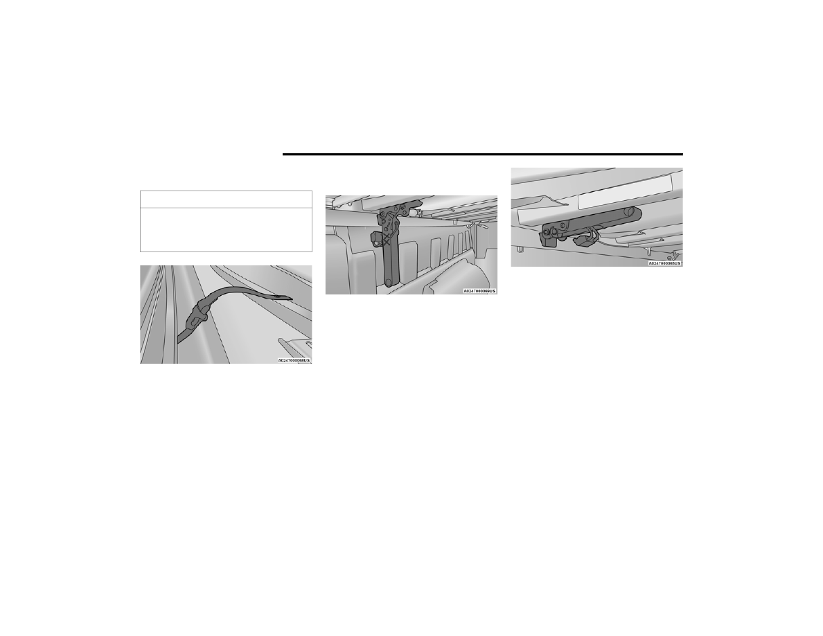
6. Clip both stowage straps to prevent the 

Tonneau Cover panels from unfolding.

Stowage Strap

7. Once in the Tri-Folded Position, pull both front 

clamp handles down to the Released Position.

Released Position

8. From the Released Position, send the clamps 

to the Stowed Position by pushing from the 

yellow bumper upward. Listen for a “clicking” 

sound to confirm the clamp has been properly 

stowed.

Stowed Position

9. Utilizing two people, remove the Tonneau 

Cover.

NOTE:

Be sure the Tonneau Cover has been folded 

completely, and the stowage straps are engaged, 

before removing the cover from the vehicle.

CAUTION!

The folded Tonneau Cover must be latched by 

both front latches and both front stowage straps 

or damage to the Tonneau Cover or vehicle may 

occur.

-------------------------------------------------------------------------------------------------------------------------------------------------------------

GETTING TO KNOW YOUR VEHICLE

93

T

RI

-F

OLD

 T

ONNEAU

 C

OVER


I

NSTALLATION

To install the Tonneau Cover follow the following 

steps:
1. Position the folded Tonneau Cover on the 

truck bed and push the cover forward against 

the front of the truck bed. The Tonneau Cover 

centers itself when placed on the vehicle.

NOTE:

Make sure to always push the Tonneau Cover all 

the way forward on the truck bed. Failure to do so 

might prevent proper clamp engagement, or 

interfere with the electronic tailgate release 

function (if equipped).

Location Of Front Latches

2. Pull down on the first set of clamp handles to 

release the clamps from the Stowed Position.

Stowed Position

3. Push clamp wires up and under the flange of 

the box (or flange of the RamBox rail, if 

equipped) to the Semi-Clamped Position.

Semi Clamped Position

4. Push clamp handles upward to the clamped 

position to properly engage the clamps.

Clamped Position

NOTE:

Once clamped, be sure the clamps are not 

improperly attached to the truck bed flange.

Improper Clamp Position

5. Disengage the stowage straps.

2

-------------------------------------------------------------------------------------------------------------------------------------------------------------

94

GETTING TO KNOW YOUR VEHICLE


6. Unfold the center and rear panels to the 

Intermediate Position.

Intermediate Position (Vehicle Cannot Be Driven)

NOTE:

When folding the center and rear panels, the 

sections MUST be held together to avoid damage 

to the cover material.

Incorrect Folding — Will Cause Damage

Correct Folding — Hold Panels Together

7. Completely unfold the Tonneau Cover.

Fully Unfolded Position

8. Pull the rear clamp handles down into the 

Released Position.

Stowed Position

9. Push clamp wires up and under the flange of 

box (or flange of RamBox rail, if equipped) to 

the Semi Clamped Position.

Semi Clamped Position

-------------------------------------------------------------------------------------------------------------------------------------------------------------

GETTING TO KNOW YOUR VEHICLE

95

10. Push clamp handles upward to the clamped 

position to properly engage the clamps.

Clamped Position

Improper Clamp Position

NOTE:

Once clamped, be sure the clamps are not partially 

clamped to the truck bed flange.

The Tonneau Cover clamps can be locked when in 

the clamped position by placing a lock through the 

locking hole.

Locking Hole

T

RI

-F

OLD

 T

ONNEAU

 C

OVER

 C

LEANING

For proper cleaning of the Tonneau Cover, use 

Mopar® Whitewall & Vinyl Top Cleaner and 

Mopar® Leather & Vinyl Conditioner/Protectant.

CAUTION!

It is the driver’s responsibility to ensure the 

Tonneau Cover is properly installed on the 

vehicle. Failure to follow this procedure can 

result in detachment of the Tonneau Cover from 

the vehicle and/or damage to the vehicle/

Tonneau Cover.

2

-------------------------------------------------------------------------------------------------------------------------------------------------------------

96  

GETTING TO KNOW YOUR INSTRUMENT PANEL

BASE / MIDLINE INSTRUMENT CLUSTER — GAS ENGINE

-------------------------------------------------------------------------------------------------------------------------------------------------------------

GETTING TO KNOW YOUR INSTRUMENT PANEL

97

B

ASE

 / M

IDLINE

 I

NSTRUMENT

 C

LUSTER


D

ESCRIPTIONS

 — G

AS

 E

NGINE

1. Tachometer

Indicates the engine speed in revolutions 

per minute (RPM x 1000).

2. Voltmeter

When the vehicle is in the RUN state, the 

gauge indicates the electrical system 

voltage. The pointer should stay within the 

normal range if the battery is charged. If the 

pointer moves to either extreme left or right 

and remains there during normal driving, 

the electrical system should be serviced.

3. Instrument Cluster Display

When the appropriate conditions exist, this 

display shows the instrument cluster 

display messages  

Ú

page 103.

The display always shows one of the main 

menu item after ignition is placed on.

4. Oil Pressure Gauge

The pointer should always indicate the oil 

pressure when the engine is running. A 

continuous high or low reading under 

normal driving conditions may indicate a 

lubrication system malfunction. Immediate 

service should be obtained from an autho

-

rized dealer.

5. Speedometer

Indicates vehicle speed.

6. Temperature Gauge

The gauge pointer shows engine coolant 

temperature. The pointer positioned within 

the normal range indicates that the engine 

cooling system is operating satisfactorily.

The gauge pointer will likely indicate a 

higher temperature when driving in hot 

weather, up mountain grades, or when 

towing a trailer. It should not be allowed to 

exceed the upper limits of the normal oper

-

ating range.

7. Fuel Gauge

The pointer shows the level of fuel in the 

fuel tank when the ignition is in the ON/RUN 

position.

 The fuel pump symbol points to the 

side of the vehicle where the fuel 

door is located.

WARNING!

A hot engine cooling system is dangerous. You or 

others could be badly burned by steam or boiling 

coolant. It is recommended to call an authorized 

dealer for service if your vehicle overheats  

Ú

page 389.

CAUTION!

Driving with a hot engine cooling system could 

damage your vehicle. If the temperature gauge 

reads “H”, pull over and stop the vehicle. Idle the 

vehicle with the air conditioner turned off until 

the pointer drops back into the normal range. If 

the pointer remains on the “H”, turn the engine 

off immediately and call an authorized dealer for 

service.

3

-------------------------------------------------------------------------------------------------------------------------------------------------------------

98

GETTING TO KNOW YOUR INSTRUMENT PANEL


PREMIUM INSTRUMENT CLUSTER — GAS ENGINE

-------------------------------------------------------------------------------------------------------------------------------------------------------------

GETTING TO KNOW YOUR INSTRUMENT PANEL

99

P

REMIUM

 I

NSTRUMENT

 C

LUSTER


D

ESCRIPTIONS

 — G

AS

 E

NGINE

1. Tachometer

Indicates the engine speed in revolutions 

per minute (RPM x 1000).

2. Instrument Cluster Display

When the appropriate conditions exist, this 

display shows the instrument cluster 

display messages  

Ú

page 103.

The display always shows one of the main 

menu item after ignition is placed on.

3. Speedometer

Indicates vehicle speed.

4. Temperature Gauge

The gauge pointer shows engine coolant 

temperature. The pointer positioned within 

the normal range indicates that the engine 

cooling system is operating satisfactorily.

The gauge pointer will likely indicate a 

higher temperature when driving in hot 

weather, up mountain grades, or when 

towing a trailer. It should not be allowed to 

exceed the upper limits of the normal oper

-

ating range.

5. Fuel Gauge

The pointer shows the level of fuel in the 

fuel tank when the ignition is in the ON/RUN 

position.

 The fuel pump symbol points to the 

side of the vehicle where the fuel 

door is located.

WARNING!

A hot engine cooling system is dangerous. You or 

others could be badly burned by steam or boiling 

coolant. It is recommended to call an authorized 

dealer for service if your vehicle overheats  

Ú

page 389.

CAUTION!

Driving with a hot engine cooling system could 

damage your vehicle. If the temperature gauge 

reads “H”, pull over and stop the vehicle. Idle the 

vehicle with the air conditioner turned off until 

the pointer drops back into the normal range. If 

the pointer remains on the “H”, turn the engine 

off immediately and call an authorized dealer for 

service.

3

-------------------------------------------------------------------------------------------------------------------------------------------------------------

100

GETTING TO KNOW YOUR INSTRUMENT PANEL


BASE INSTRUMENT CLUSTER — DIESEL ENGINE 

B

ASE

 I

NSTRUMENT

 C

LUSTER


D

ESCRIPTIONS

 — D

IESEL

 E

NGINE

1. Tachometer

Indicates the engine speed in revolutions 

per minute (RPM x 1000).

2. Engine Coolant Temperature

This gauge shows the engine coolant 

temperature. The gauge pointer will likely 

show higher temperatures when driving in 

hot weather, up mountain grades, or in 

heavy stop and go traffic. If the red Warning 

Light turns on while driving, safely bring the 

vehicle to a stop, and turn off the engine. 

DO NOT operate the vehicle until the cause 

is corrected.

-------------------------------------------------------------------------------------------------------------------------------------------------------------

GETTING TO KNOW YOUR INSTRUMENT PANEL

101

3. Instrument Cluster Display

When the appropriate conditions exist, this 

display shows the instrument cluster 

display messages  

Ú

page 103.

The display always shows one of the main 

menu item after ignition is placed on.

4. Oil Pressure Gauge

The pointer should always indicate some oil 

pressure when the engine is running. A 

continuous high or low reading under 

normal driving conditions may indicate a 

lubrication system malfunction. Immediate 

service should be obtained from an autho

-

rized dealer.

5. Speedometer

Indicates vehicle speed.

6. Diesel Exhaust Fluid (DEF) Gauge

The DEF Gauge displays the actual level of 

Diesel Exhaust Fluid in the DEF tank. DEF is 

required to maintain normal vehicle opera

-

tion and emissions compliance. If some

-

thing is wrong with the gauge, a DEF 

Warning Message or Malfunction Indicator 

Light (MIL) will be displayed. More informa

-

tion is available in the instrument cluster 

display section under the heading of DEF 

Warning Messages.

NOTE:

The gauge may take up to five seconds to 

update after adding a gallon or more of DEF 

to the DEF tank. If you have a fault related 

to the DEF system, the gauge may not 

update to the new level. See an authorized 

dealer for service.

The DEF gauge may also not immediately 

update after a refill if the temperature of the 

DEF fluid is below 39°F (4°C). The DEF tank 

heater will warm up the DEF fluid and allow 

the gauge to update after a period of run 

time. Under very cold conditions, it is 

possible that the gauge may not reflect the 

new fill level for several drives.

7. Fuel Gauge

The pointer shows the level of fuel in the 

fuel tank when the ignition switch is in the 

ON/RUN position.

 The fuel pump symbol points to the 

side of the vehicle where the fuel 

filler door is located.

WARNING!

A hot engine cooling system is dangerous. You or 

others could be badly burned by steam or boiling 

coolant. It is recommended to call an authorized 

dealer for service if your vehicle overheats.

CAUTION!

Driving with a hot engine cooling system could 

damage your vehicle. If the temperature gauge 

reads greater “H”, pull over and stop the vehicle. 

Idle the vehicle with the air conditioner turned 

off until the pointer drops back into the normal 

range. If the pointer remains on the “h”, turn the 

engine off immediately and call an authorized 

dealer for service.

3

-------------------------------------------------------------------------------------------------------------------------------------------------------------

102

GETTING TO KNOW YOUR INSTRUMENT PANEL


PREMIUM INSTRUMENT CLUSTER — DIESEL ENGINE 

P

REMIUM

 I

NSTRUMENT

 C

LUSTER


D

ESCRIPTIONS

 — D

IESEL

 E

NGINE

1. Tachometer

Indicates the engine speed in revolutions 

per minute (RPM x 1000).

2. Instrument Cluster Display

When the appropriate conditions exist, this 

display shows the instrument cluster 

display messages  

Ú

page 103.

The display always shows one of the main 

menu item after ignition is placed on.

3. Speedometer

Indicates vehicle speed.

-------------------------------------------------------------------------------------------------------------------------------------------------------------

GETTING TO KNOW YOUR INSTRUMENT PANEL

103

4. Diesel Exhaust Fluid (DEF) Gauge

The DEF Gauge displays the actual level of 

Diesel Exhaust Fluid in the DEF tank. DEF is 

required to maintain normal vehicle opera

-

tion and emissions compliance. If some

-

thing is wrong with the gauge, a DEF 

Warning Message or Malfunction Indicator 

Light (MIL) will be displayed. More informa

-

tion is available in the instrument cluster 

display section under the heading of DEF 

Warning Messages.

NOTE:

The DEF tank on these vehicles is designed 

with a large amount of full reserve. So the 

level sensor will indicate a full reading even 

before the tank is completely full. To put it 

another way, there’s additional storage 

capacity in the tank above the Full mark 

that’s not represented in the gauge. You 

may not see any movement in the reading – 

even after driving up to 200 miles (322 kilo

-

meters) in some cases.

The gauge may take up to five seconds to 

update after adding a gallon or more of DEF 

to the DEF tank. If you have a fault related 

to the DEF system, the gauge may not 

update to the new level. See an authorized 

dealer for service.

The DEF gauge may also not immediately 

update after a refill if the temperature of the 

DEF fluid is below 39°F (4°C). The DEF tank 

heater will warm up the DEF fluid and allow 

the gauge to update after a period of run 

time. Under very cold conditions, it is 

possible that the gauge may not reflect the 

new fill level for several drives.

5. Fuel Gauge

The pointer shows the level of fuel in the 

fuel tank when the ignition switch is in the 

ON/RUN position.

 The fuel pump symbol points to the 

side of the vehicle where the fuel 

filler door is located.

INSTRUMENT CLUSTER DISPLAY 

Your vehicle is equipped with an instrument cluster 

display, which offers useful information to the 

driver. With the ignition in the OFF mode, opening/

closing of a door will activate the display for 

viewing, and display the total miles, or kilometers, 

in the odometer. Your instrument cluster display is 

designed to display important information about 

your vehicle’s systems and features. Using a driver 

interactive display located on the instrument 

panel, your instrument cluster display can show 

you how systems are working and give you 

warnings when they are not. The steering wheel 

mounted controls allow you to scroll through the 

main menus and submenus. You can access the 

specific information you want and make selections 

and adjustments.

I

NSTRUMENT

 C

LUSTER

 D

ISPLAY


C

ONTROLS

The instrument cluster display features a driver 

interactive display that is located in the instrument 

cluster.

Instrument Cluster Display Location and Controls

1 – Instrument Cluster Display Controls
2 – Instrument Cluster Display Screen

3

-------------------------------------------------------------------------------------------------------------------------------------------------------------

104

GETTING TO KNOW YOUR INSTRUMENT PANEL


The system allows the driver to select information 

by pushing the following instrument cluster display 

control buttons located on the left side of the 

steering wheel:

Instrument Cluster Display Control Buttons

Up Arrow Button
Push and release the up   arrow button to 

scroll upward through the main menu items, 

submenu screen, and vehicle settings.

Right Arrow Button
Push and release the right   arrow button to 

access/select the information screens or 

submenu screens of a main menu item. Push 
and hold the right   arrow button for two 

seconds to reset displayed/selected features 

that can be reset.

Down Arrow Button
Push and release the down   arrow button to 

scroll downward through the main menu items, 

submenu screen, and vehicle settings.

Left Arrow Button
Push and release the left   arrow button to 

access/select the information screens, 

submenu screens of a main menu item, or to 

return to the main menu.

O

IL

 L

IFE

 R

ESET


Your vehicle is equipped with an engine oil change 

indicator system. The “Oil Change Required” 

message will display in the instrument cluster 

display after a single chime has sounded, to 

indicate the next scheduled oil change interval. 

The engine oil change indicator system is duty 

cycle based, which means the engine oil change 

interval may fluctuate, dependent upon your 

personal driving style.
NOTE:

Use the steering wheel instrument cluster display 

controls for the following procedure.

Oil Life Reset Procedure
1. Without pushing the brake pedal, push the 

ENGINE START/STOP button and place the 

ignition to the ON/RUN position (do not start 

the engine).

2. Push and release the down   arrow button to 

scroll downward through the main menu to 

“Vehicle Info.”

3. Push and release the right   arrow button to 

access the ”Vehicle Info” screen, then scroll up 

or down to select “Oil Life.”

4. Push and hold the right   arrow button to 

select “Reset”.

5. Push and release the down   arrow button to 

select “Yes,” then push and release the 
right   arrow button to reset the Oil Life to 

100%.

6. Push and release the up   arrow button to 

exit the instrument cluster display screen.

Secondary Method Of Resetting Engine Oil Life
1. Without pressing the brake pedal, push the 

ENGINE START/STOP button and place the 

ignition to the ON/RUN position (do not start 

the engine).

2. Fully press the accelerator pedal, slowly, three 

times within ten seconds.

1 – Up Arrow Button
2 – Right Arrow Button
3 – Down Arrow Button
4 – Left Arrow Button

-------------------------------------------------------------------------------------------------------------------------------------------------------------

GETTING TO KNOW YOUR INSTRUMENT PANEL

105

3. Without pushing the brake pedal, push the 

ENGINE START/STOP button once to return the 

ignition to the OFF position.

NOTE:

If the indicator message illuminates when you start 

the vehicle, the oil change indicator system did not 

reset. If necessary, repeat this procedure.

D

ISPLAY

 M

ENU

 I

TEMS

Push and release the up   or down   arrow 

button until the desired selectable menu icon is 

highlighted in the instrument cluster display.

Speedometer

Push and release the up   or down   arrow 

button until the speedometer menu item is 

highlighted in the instrument cluster display. Push 
and release the right   arrow button to cycle the 

display between mph and km/h.

Vehicle Info

Push and release the up   or down   arrow 

button until the Vehicle Info menu item is 

highlighted in the instrument cluster display. Push 
and release the right   arrow button to enter the 

submenus items of Vehicle Info. Follow the 

directional prompts to access or reset any of the 

following Vehicle Info submenu items:

Tire Pressure

Coolant Temperature

Transmission Temperature — If Equipped

Oil Temperature

Oil Pressure

Exhaust Brake — If Equipped

Boost Pressure — If Equipped

Diesel Particulate Filter — If Equipped

Oil Life

Fuel Filter Life — If Equipped

Battery Voltage

Gauge Summary

Engine Hours

Driver Assist — If Equipped

The Driver Assist menu displays the status of the 

Adaptive Cruise Control (ACC) and LaneSense 

systems.
Push and release the up   or down   arrow 

button until the Driver Assist menu is displayed in 

the instrument cluster display.
Adaptive Cruise Control (ACC) Feature
The instrument cluster display displays the current 

ACC system settings. The information displayed 

depends on ACC system status.

Push the ACC on/off button (located on the 

steering wheel) until one of the following displays 

in the instrument cluster display:
Adaptive Cruise Control Off
When ACC is deactivated, the display will read 

“Adaptive Cruise Control Off.”
Adaptive Cruise Control Ready
When ACC is activated but the vehicle speed 

setting has not been selected, the display will read 

“Adaptive Cruise Control Ready.”
Push the SET + or the SET- button (located on the 

steering wheel) and the following will display in the 

instrument cluster display:
ACC SET
When ACC is set, the set speed will display in the 

instrument cluster  

Ú

page 115.

The ACC screen may display once again if any ACC 

activity occurs, which may include any of the 

following: 

Distance Setting Change

System Cancel

Driver Override

System Off

ACC Proximity Warning

ACC Unavailable Warning

3

-------------------------------------------------------------------------------------------------------------------------------------------------------------

106

GETTING TO KNOW YOUR INSTRUMENT PANEL


LaneSense — If Equipped
The instrument cluster display displays the current 

LaneSense system settings. The information 

displayed depends on LaneSense system status 

and the conditions that need to be met.

Fuel Economy

Push and release the up   or down   arrow 

button until the Fuel Economy menu item is 

highlighted in the instrument cluster display. Push 
and Hold the right   arrow button to reset 

Average Fuel Economy.

Current Fuel Economy Gauge

Average Fuel Economy Value

Range To Empty

Off Road

Push and release the up   or down   arrow 

button until the Off Road menu icon is displayed in 

the instrument cluster display. Push and release 
the left   or right   arrow button to scroll 

through the information submenus.

Drivetrain

Front Wheel Angle: displays the graphical 

and numerical value of calculated average 

front wheel angle from the steering wheel 

orientation.

Transfer Case Lock Status: displays “Lock” 

graphic only during 4WD High, 4WD High 

Part Time, 4WD Low status.

Axle Lock And Sway Bar Status (If 

Equipped): displays front and rear or rear 

only axle locker graphic, and sway bar 

connection graphic with text message 

(connected or disconnected).

Pitch And Roll

Displays the pitch and roll of the vehicle in 

the graphic with the angle number on the 

screen.

NOTE:

When vehicle speed becomes too high to display 

the pitch and roll, “- -” will display in place of the 

numbers, and the graphic will be greyed out. A 

message indicating the necessary speed for the 

feature to become available will also display.

Trip A/Trip B

Push and release the up   or down   arrow 

button until the Trip menu item is highlighted in the 

instrument cluster display. Push and release the 
right   arrow button to enter the submenus of 

Trip A and Trip B. The Trip A or Trip B information 

will display the following:

Distance

Average Fuel Economy

Elapsed Time

Push and hold the right   arrow button to reset all 

information.

Trailer Tow

Push and release the up   or down   arrow 

button until the Trailer Tow menu item is 

highlighted in the instrument cluster display. Push 
and release the right   or left   arrow button to 

cycle through the following trailer tow information:

Trip (trailer specific) Distance: Push and hold 

the OK button to reset the distance.

Integrated Trailer Brake Module (ITBM):

Braking Output

Trailer Type

ITBM Gain

Trailer Light Check: Push and hold the OK 

button to begin the Trailer Light Test sequence  

Ú

page 221.

Trailer Tire Pressure Monitoring: The Instrument 

Cluster Display will display the Trailer Tire Pres

-

sure for a connected trailer with sensors that 

match the active trailer profile. When a low tire 

is present, the low tire value will be displayed in 

red, and the affected low tire will have a red 

glow. “Trailer Tire Low“ will be displayed on the 

center bottom of the Instrument Cluster Display 

screen.

-------------------------------------------------------------------------------------------------------------------------------------------------------------

GETTING TO KNOW YOUR INSTRUMENT PANEL

107

Audio

Push and release the up   or down   arrow 

button until the Audio Menu icon/title is 

highlighted in the instrument cluster display. This 

menu will display the audio source information, 

including the Song name, Artist name, and audio 

source with an accompanying graphic.
Phone Call Status
When a call is incoming, a Phone Call Status 

pop-up will display on the screen. The pop-up will 

remain until the phone is answered or ignored.
NOTE:

The call status will temporarily replace the 

previous media source information displayed on 

the screen. When the pop-up is no longer 

displayed, the display will return to the last used 

screen.

Messages

Push and release the up   or down   arrow 

button until the Messages Menu item is 

highlighted. This feature shows the number of 

stored warning messages. Push and release the 
right   or left   arrow button to cycle through 

stored messages.

Screen Setup Menu Item

Push and release the up   or down   arrow 

button until the Screen Setup menu item is 

highlighted in the instrument cluster display. Push 
and release the right   arrow button to enter the 

Screen Setup submenu. The Screen Setup feature 

allows you to change what information is displayed 

in the instrument cluster as well as the location 

that information is displayed.
Current Gear

Off

On

Odometer

Unit Without Decimal

Unit With Decimal

NOTE:
Menus with (Show/Hide) can push the right   

arrow button to choose whether to show or hide 

this menu in the instrument cluster display.

Favorite Menu

Speedometer

Audio

(Show/Hide)

Vehicle Info

Driver Assist 

(Show/Hide) — 

If Equipped

Screen Setup Fuel Economy 

(Show/Hide)

Trip Info 

(Show/Hide)

Commercial 

Settings — 

If Equipped

Trailer Tow 

(Show/Hide)

Messages

Vehicle 

Settings — 

If Equipped

Upper Left and Upper Right

None

Trip B Distance

Oil Life —

If Equipped

Outside Temp 

— If Equipped

Trailer Brake — 

If Equipped

Turbo Boost — 

If Equipped

Range To 

Empty

Coolant 

Temperature — 

If Equipped

Compass —

If Equipped

Current MPG

Battery 

Voltage — 

If Equipped

Time

Average MPG Trip A Distance Trailer Trip — 

If Equipped

Favorite Menu

3

-------------------------------------------------------------------------------------------------------------------------------------------------------------


Content      ..     4      5      6      7     ..