RAM 1500 (2022 year). Manual in english - page 6
 

  Index      Manuals     RAM 1500 (2022 year). Manual in english


Search            copyright infringement  


Content      ..     4      5      6      7     ..


RAM 1500 (2022 year). Manual in english - page 6


GETTING TO KNOW YOUR VEHICLE

91

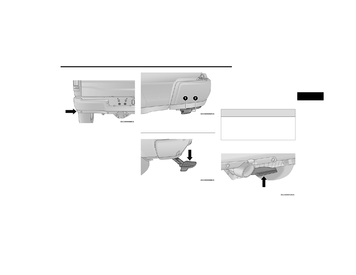
Bed Step For Standard Tailgate

Bed Step Location

To extend the bed step, place your foot on the 

protruding foot tab located on the left edge of the 

bed step, and push rearward. A small amount of 

force will release the spring load and extend the 

bed step out and away from the tailgate.

Bed Step Components (Standard Tailgate)

Bed Step Extended

NOTE:

Once the spring load is overcome, the bed step will 

extend out quickly, so be sure to stand in a position 

that will avoid coming into contact with the step as 

it extends.
To stow the bed step back under the tailgate, push 

the bed step forward with your foot until the bed 

step is retracted by the spring load.

Bed Step For Multifunction Tailgate

Bed Step Location

1 — Bed Step
2 — Foot Tab

WARNING!

Do not attempt to stow the bed step with your 

hands. The low clearance space between the 

bed step and the rear bumper as the bed step 

returns to the stowed position could result in 

injury to your hands or fingers.

2

-------------------------------------------------------------------------------------------------------------------------------------------------------------

92

GETTING TO KNOW YOUR VEHICLE


(Continued)

To extend the bed step, place your foot on the top 

center of the bed step, and push down while 

pulling rearward. A small amount of force will 

release the spring load and extend the bed step 

out and away from the tailgate.

Bed Step Extended

NOTE:

Once the spring load is overcome, the bed step will 

extend out quickly. Be sure to stand in a position 

that will avoid coming into contact with the step as 

it extends.
To stow the bed step back under the tailgate, push 

the bed step forward with your foot until the bed 

step is retracted by the spring load.

PICKUP BOX 

The pickup box has many features designed for 

utility and convenience.

Pickup Box Features

NOTE:

If you are installing a Toolbox, Ladder Rack or 

Headache Rack at the front of the Pickup Box, you 

must use Mopar® Box Reinforcement Brackets 

that are available from an authorized dealer.
You can carry wide building materials (sheets of 

plywood, etc.) by building a raised load floor. Place 

lumber across the box in the indentations provided 

above the wheel housings and in the bulkhead 

dividers to form the floor.

WARNING!

Do not attempt to stow the bed step with your 

hands. The low clearance space between the 

bed step and the rear bumper as the bed step 

returns to the stowed position could result in 

injury to your hands or fingers.

1 — Upper Load Floor Indents
2 — Bulk Head Dividers
3 — Cleats

WARNING!

The pickup box is intended for load carrying 

purposes only, not for passengers, who should 

sit in seats and use seat belts.

Care should always be exercised when oper

-

ating a vehicle with unrestrained cargo. 

Vehicle speeds may need to be reduced. 

Severe turns or rough roads may cause 

shifting or bouncing of the cargo that may 

result in vehicle damage. If wide building 

materials are to be frequently carried, the 

installation of a support is recommended. This 

will restrain the cargo and transfer the load to 

the pickup box floor.

-------------------------------------------------------------------------------------------------------------------------------------------------------------

GETTING TO KNOW YOUR VEHICLE

93

There are stampings in the sheet metal on the 

inner side bulkheads of the box in front of and 

behind both wheel housings. Place wooden boards 

across the box from side to side to create separate 

load compartments in the pickup box.
There are four tie-down cleats bolted to the lower 

sides of the pickup box that can sustain loads up 

to 1,000 lb (450 kg) total.

B

ED

 R

AIL

 T

IE

-D

OWN

 S

YSTEM

 —

I

F

 E

QUIPPED


There are two adjustable cleats on each side of the 

bed that can be used to assist in securing cargo.

Adjustable Cleats

Each cleat must be located and tightened down in 

one of the detents, along either rail, in order to 

keep cargo properly secure.
To move the cleat to any position on the rail, turn 

the nut counterclockwise, approximately three 

turns. Then pull out on the cleat and slide it to the 

detent nearest the desired location. Make sure the 

cleat is seated in the detent and tighten the nut.

Adjustable Cleat Assembly

If you wish to carry more than 600 lb (272 kg) 

of material suspended above the wheelhouse, 

supports must be installed to transfer the 

weight of the load to the pickup box floor or 

vehicle damage may result. The use of proper 

supports will permit loading up to the rated 

payload.

Unrestrained cargo may be thrown forward in 

an accident causing serious or fatal injury.

WARNING!

CAUTION!

The maximum load per cleat should not exceed 

250 lb (113 kg), or 500 lb (227 kg) total per rail, 

and the angle of the load on each cleat should 

not exceed 45 degrees above horizontal, or 

damage to the cleat or cleat rail may occur.

1 — Utility Rail Detent
2 — Cleat Retainer Nut
3 — Utility Rail Cleat

2

-------------------------------------------------------------------------------------------------------------------------------------------------------------

94

GETTING TO KNOW YOUR VEHICLE


Cleat Removal (Standard Box Rail)
To remove the cleats from the utility rail, slide the 

cleat forward to access the cut out at the end of the 

box rail, then remove the cleat.

Slide Cleat Forward To Remove

Cleat Removal (With Tonneau Cover)
To remove the cleats from the utility rail, remove 

the end cap screw located in the center of the end 

cap, using a #T30 Torx head driver. Remove the 

end cap and slide the cleat off the end of the rail.

End Cap Screw Location With Tonneau Cover

Cleat Removal (Without Tonneau Cover)
Remove the end cap by pushing upward on the 

release button located beneath the end cap while 

pulling the cap away from the rail. The cleat can 

now be removed by sliding it off the end of the rail.

End Cap Release Button Without Tonneau Cover

Pull End Cap Away From Rail

RAMBOX — IF EQUIPPED  

The RamBox system is an integrated pickup box 

storage and cargo management system consisting 

of three features:

Cargo storage bins

Cargo divider

Bed rail tie-down system  

Ú

page 93

NOTE:

Bed rail tie-down system is also available for 

vehicles not equipped with a RamBox.

-------------------------------------------------------------------------------------------------------------------------------------------------------------

GETTING TO KNOW YOUR VEHICLE

95

L

OCKING

 A

ND

 U

NLOCKING

 R

AM

B

OX

Push and release the lock or unlock button on the 

key fob to lock and unlock all doors, the tailgate 

and the RamBox  

Ú

page 19. To unlatch the 

storage bin manually, insert the emergency key 

into the keyhole and turn clockwise. Always return 

the key to the upright (vertical) position before 

removing it from the keyhole.

R

AM

B

OX

 C

ARGO

 S

TORAGE

 B

INS

Cargo storage bins are located on both sides of the 

pickup box. The cargo storage bins provide 

watertight, lockable, illuminated storage for up to 

150 lb (68 kg) of evenly distributed cargo.

RamBox Cargo Storage Bins

To open a storage bin with the RamBox unlocked, 

push and release the button located on the lid. The 

RamBox lid will open upward to allow hand access. 

Lift the lid to fully open.

NOTE:

RamBox will not open when the button is pushed if 

the RamBox is locked.

RamBox Button And Keyhole Lock

CAUTION!

Ensure cargo bin lids are closed and latched 

before moving or driving vehicle.

Loads applied to the top of the bin lid should 

be minimized to prevent damage to the lid and 

latching/hinging mechanisms.

Damage to the RamBox bin may occur due to 

heavy/sharp objects placed in bin that shift 

due to vehicle motion. In order to minimize 

potential for damage, secure all cargo to 

prevent movement and protect inside 

surfaces of bin from heavy/sharp objects with 

appropriate padding.

CAUTION!

Failure to follow the following items could cause 

damage to the vehicle:

Assure that all cargo inside the storage bins is 

properly secured.

Do not exceed cargo weight rating of 150 lb 

(68 kg) per bin.

1 — Keyhole Lock
2 — Button

2

-------------------------------------------------------------------------------------------------------------------------------------------------------------

96

GETTING TO KNOW YOUR VEHICLE


The interior of the RamBox will automatically 

illuminate when the lid is opened. The timing can 

be adjusted within Uconnect Settings  

Ú

page 237.

Cargo bins feature two removable drain plugs (to 

allow water to drain from bins). To remove plug, 

pull up on the edge. To install, push plug downward 

into drain hole.

RamBox Drain Plug Removal

NOTE:

Provisions are provided in the bins for cargo 

dividers. These accessories (in addition to other 

RamBox accessories) are available from Mopar®.
If equipped, a 115 Volt (400 Watts Maximum) 

inverter may be located inside the RamBox of your 

vehicle. The inverter can be turned on by the 

Instrument Panel Power Inverter switch located to 

the left of the steering wheel. The RamBox inverter 

can power cellular phones, electronics and other 

low power devices requiring power up to 400 

Watts. Certain video game consoles exceed this 

power limit, as will most power tools.

RamBox Power Inverter

The Instrument Panel Power Inverter switch is only 

found on vehicles equipped with a RamBox. The 

switch only controls on/off operation of the power 

outlet in the RamBox; it does not control on/off 

operation of the power outlets located inside the 

cabin of the vehicle.

Instrument Panel Power Inverter Switch

CAUTION!

Leaving the lid open for extended periods of time 

could cause the vehicle battery to discharge. If 

the lid is required to stay open for extended 

periods of time, it is recommended that the bin 

lights be turned off manually using the on/off 

switch.

-------------------------------------------------------------------------------------------------------------------------------------------------------------

GETTING TO KNOW YOUR VEHICLE

97

R

AM

B

OX

 S

AFETY

 W

ARNING

Carefully follow these warnings to help prevent 

personal injury or damage to your vehicle:

RamBox Emergency Release Lever

As a security measure, an Emergency Release 

Lever is built into the storage bin cover latching 

mechanism.

In the event of an individual being locked inside 

the storage bin, the storage bin cover can be 

opened from inside of the bin by pulling on the 

glow-in-the-dark lever attached to the storage bin 

cover latching mechanism.

Emergency Release Lever

B

ED

 D

IVIDER

 — I

F

 E

QUIPPED

The bed divider has two functional positions:

Divider Position

Storage Position

Divider Position

The divider position is intended for managing your 

cargo and assisting in keeping cargo from moving 

around the bed. There are 11 divider slots along 

the bed inner panels which allow for various 

positions to assist in managing your cargo.

To install the bed divider into a divider position, 

perform the following:
1. Make sure the center handle is unlocked 

using the vehicle key and rotate the center 

handle vertically to release the divider side 

gates.

Center Handle And Lock

WARNING!

Always close the storage bin covers when your 

vehicle is unattended.

Do not allow children to have access to the 

storage bins. Once in the storage bin, young 

children may not be able to escape. If trapped 

in the storage bin, children can die from suffo

-

cation or heat stroke.

In an accident, serious injury could result if the 

storage bin covers are not properly latched.

Do not drive the vehicle with the storage bin 

covers open.

Keep the storage bin covers closed and 

latched while the vehicle is in motion.

Do not use a storage bin latch as a tie-down.

1 — Center Handle Lock
2 — Handle
3 — Unlocked Position
4 — Locked Position

2

-------------------------------------------------------------------------------------------------------------------------------------------------------------

98

GETTING TO KNOW YOUR VEHICLE


2. With the side gates open, position the divider 

so the outboard ends align with the intended 

slots in the sides of the bed.

Aligning Gate To Slots

3. Rotate the side gates closed so that the 

outboard ends are secured into the intended 

slots of the bed.

4. Rotate the center handle horizontally to secure 

the side gates in the closed position.

Side Gates Closed

5. Lock the center handle to secure the panel 

into place.

Storage Position

The storage position for the bed divider is at the 

front of the truck bed which maximizes the bed 

cargo area when not in use.
To install the bed divider into the storage position, 

perform the same steps as you would for the 

divider position, except position the divider fully 

forward in the bed against the front panel.

Storage Position

The outboard ends should be positioned in front of 

the cargo tie-down loops.

Cargo Tie-Down Loop

-------------------------------------------------------------------------------------------------------------------------------------------------------------

GETTING TO KNOW YOUR VEHICLE

99

TRI-FOLD TONNEAU COVER — IF EQUIPPED 

The Tri-Fold Tonneau Cover can be installed on the 

truck bed to protect your gear and cargo.

T

ONNEAU

 C

OVER

 C

OMPONENTS

Folded Tonneau Cover Components

Tonneau Cover Latch Components

Position One (Front Latches Latched And Stowage

Straps Secured)

Position Two (Front And Rear Latches Latched)

1 – Stowage Strap
2 – Tonneau Cover Bumper Folded

1 — Handle
2 — Slide Locking Lever
3 — Locating Bumper
4 — Truck Flange Bead
5 — Latch Bumper
6 — J Hook

1 — Panel 1
2 — Panel 2
3 — Panel 3

2

-------------------------------------------------------------------------------------------------------------------------------------------------------------

100

GETTING TO KNOW YOUR VEHICLE


T

RI

-F

OLD

 T

ONNEAU

 C

OVER

 F

OLDING


F

OR

 D

RIVING

 O

R

 R

EMOVAL

To remove the Tonneau Cover use the following 

steps:
1. Open the tailgate to access the rear pair of 

Tonneau Cover latches located on the 

underside of the Cover.

Location Of Rear Latches

Slide Locking Lever Inward

2. Slide the locking lever toward the inside of the 

truck bed to release the J Hook and pull the 

handle downward into the released position.

Unlatching Latch

Released Position

Hold The Bumper And Push The Handle Up

-------------------------------------------------------------------------------------------------------------------------------------------------------------

GETTING TO KNOW YOUR VEHICLE

101

3. Holding the bumper, push the fully released 

latch to the center and push up. Push the 

handle firmly, locking it into the stowed 

position. Repeat Steps 2 and 3 for the 

opposite side latch.

Stowed Position

Lift Panel 3 And Fold Onto Panel 2

4. Lift up on Panel 3 and fold it onto Panel 2.

Correct Folding — Hold Panels Together

NOTE:

When folding the second and third panels, the 

sections MUST be held together to avoid damage 

to the cover material. Fold the panel gently. Do not 

allow the panels to drop under their own weight.

Incorrect Folding — Will Cause Damage

5. Lift up on the second and third panel and fold 

them onto the first panel.

Stowage Strap Clipped

6. Unsnap the stowage strap and clip. Repeat for 

both straps to prevent the Tonneau Cover 

panels from unfolding.

Position One (Front Latches Latched And Stowage

Straps Secured)

2

-------------------------------------------------------------------------------------------------------------------------------------------------------------

102

GETTING TO KNOW YOUR VEHICLE


NOTE:

Be sure the Tonneau Cover has been folded 

completely, and the stowage straps are engaged, 

before removing.

Fully Folded Tonneau Cover

NOTE:

The vehicle can be driven with the Tonneau Cover 

in the folded position or can be completely 

removed.

Slide Locking Lever Inward

7. Slide the locking lever toward the inside of the 

truck bed to release the J Hook and pull the 

handle downward into the released position.

Unlatching Latch

Released Position

Hold The Bumper And Push The Handle Up

CAUTION!

The folded Tonneau Cover must be latched by 

both front latches and both front stowage straps 

or damage to the Tonneau Cover or vehicle may 

occur while driving.

-------------------------------------------------------------------------------------------------------------------------------------------------------------

GETTING TO KNOW YOUR VEHICLE

103

8. Holding the bumper, push the fully released 

latch to the center and push up. Push the 

handle firmly, locking it into the stowed 

position. Repeat Steps 2 & 3 for the opposite 

side latch.

9. With two people, remove the cover.

T

RI

-F

OLD

 T

ONNEAU

 C

OVER


I

NSTALLATION

To install the Tonneau Cover follow these steps:
1. Position the Tonneau Cover on the truck bed 

and center using the locating bumpers.

2. Locate the front pair of Tonneau Cover latches 

on the underside of the Cover. Slide the 

locking lever toward the inside of the truck bed 

and release the latch from the stowed 

position, and pull the handle downward into 

the released position. Do this for both the left 

and right side.

Location of Front Latches

Slide Locking Lever Towards Inside Of Truck

Unlatching Latch

Released Position

2

-------------------------------------------------------------------------------------------------------------------------------------------------------------

104

GETTING TO KNOW YOUR VEHICLE


3. Swing the J Hook from the handle and push 

the handle to the center and up, ensuring that 

the J Hook is under the truck flange. Push up 

on the handle firmly, locking it into the latched 

position.

J Hook Under Truck Flange

NOTE:

Make sure the bumper is in front of the truck 

flange bead.

Pull Handle Downward

4. Pull down on the handle to ensure the Slide 

Locking Lever is fully engaged. Do this for both 

the left and right side.

5. Unclip the stowage straps, and re-snap them 

to the bow.

6. Unfold the Tonneau Cover to the second panel 

position.

Incorrect Folding — Will Cause Damage

NOTE:

When folding the second and third panels, the 

sections MUST be held together to avoid damage 

to the cover material. Fold the panel gently. Do not 

allow the panels to drop under their own weight.

Second Panel Position

1 — Front Of Truck
2 — J Hook

-------------------------------------------------------------------------------------------------------------------------------------------------------------

GETTING TO KNOW YOUR VEHICLE

105

NOTE:

Unfold the panel gently, and do not allow the 

panels to drop under their own weight.
7. Completely unfold the Tonneau Cover.

Position Two (Fully Unfolded)

8. Repeat steps 2 through 3 for the rear pair of 

latches.

9. Pull down on the handle to ensure the Slide 

Locking Lever is fully engaged. Do this for both 

the left and right side.

NOTE:

Also check to ensure the bumper is forward of the 

bead on the underside of the truck flange. Make 

sure that the Tonneau Cover is positioned fully 

forward, so that the bumper clears the bead.

Pull Up On Tonneau Cover Corners

10. Gently pull up on all four corners of the 

Tonneau Cover to ensure that it is properly 

latched.

T

RI

-F

OLD

 T

ONNEAU

 C

OVER

 C

LEANING

For proper cleaning of the Tonneau Cover, use 

Mopar® Whitewall & Vinyl Top Cleaner and 

Mopar® Leather & Vinyl Conditioner/Protectant.

CAUTION!

The vehicle cannot be driven when the Tonneau 

Cover is in the second panel position.

CAUTION!

It is the driver’s responsibility to ensure the 

Tonneau Cover is properly installed on the 

vehicle. Failure to follow this procedure can 

result in detachment of the Tonneau Cover from 

the vehicle and/or damage to the vehicle/

Tonneau Cover.

2

-------------------------------------------------------------------------------------------------------------------------------------------------------------

106  

GETTING TO KNOW YOUR INSTRUMENT PANEL

BASE / MIDLINE INSTRUMENT CLUSTER — GASOLINE

-------------------------------------------------------------------------------------------------------------------------------------------------------------


Content      ..     4      5      6      7     ..