RAM 5500 Chassis Cab (2021 year). Manual in english - page 5
 

  Index      Manuals     RAM 5500 Chassis Cab (2021 year). Manual in english


Search            copyright infringement  


Content      ..     3      4      5      6     ..


RAM 5500 Chassis Cab (2021 year). Manual in english - page 5


74

GETTING TO KNOW YOUR VEHICLE


Power Outlet Fuse Locations:

F104 Fuse 20 A Yellow UCI Port/ USB Rear 

Center Console

F90 Fuse 20 A Yellow Instrument Panel 

Power Outlet Battery Fed (If Equipped)

F91 Fuse 20 A Yellow Instrument Panel 

Power Outlet Ignition Fed (If Equipped)

F93 Fuse 20 A Yellow Cigar Lighter/ Instru

-

ment Panel Power Outlet (If Equipped)

When the vehicle is turned off, be sure to unplug any 

equipment as to not drain the battery of the vehicle. 

All accessories connected to the outlet(s) should be 

removed or turned off when the vehicle is not in use 

to protect the battery against discharge.

P

OWER

 I

NVERTER

 — I

F

 E

QUIPPED


If equipped, a 115 Volt (400 Watts Maximum) 

inverter may be located inside the center console 

towards the right hand side, just under the 

Wireless Charging Pad (if equipped). This inverter 

can power cellular phones, electronics and 

other low power devices requiring power up

to 400 Watts. Certain high-end video game 

consoles exceed this power limit, as will most 

power tools.

Center Console Power Inverter Outlet

There is also a second 115 Volt (400 Watts 

Maximum) power inverter located on the rear of 

the center console. This inverter can power 

cellular phones, electronics and other low 

power devices requiring power up to 400 Watts. 

WARNING!

To avoid serious injury or death:

Only devices designed for use in this type of 

outlet should be inserted into any 12 Volt outlet.

Do not touch with wet hands.

Close the lid when not in use and while 

driving the vehicle.

If this outlet is mishandled, it may cause an 

electric shock and failure.

CAUTION!

Many accessories that can be plugged in 

draw power from the vehicle's battery, even 

when not in use (i.e., cellular phones, etc.). 

Eventually, if plugged in long enough, the 

vehicle's battery will discharge sufficiently 

to degrade battery life and/or prevent the 

engine from starting.

Accessories that draw higher power 

(i.e., coolers, vacuum cleaners, lights, etc.), 

will discharge the battery even more 

quickly. Only use these intermittently and 

with greater caution.

After the use of high power draw accesso

-

ries, or long periods of the vehicle not being 

started (with accessories still plugged in), 

the vehicle must be driven a sufficient 

length of time to allow the generator to 

recharge the vehicle's battery.

-------------------------------------------------------------------------------------------------------------------------------------------------------------

GETTING TO KNOW YOUR VEHICLE

75

Certain high-end video game consoles exceed 

this power limit, as will most power tools.
All power inverters are designed with built-in 

overload protection. If the power rating of 400 Watts 

is exceeded, the power inverter shuts down. Once 

the electrical device has been removed from the 

outlet the inverter should reset.

Rear Center Console Power Inverter Outlet

NOTE:

400 Watts is the maximum for the inverter, not each 

outlet. If three outlets are in use, 400 Watts is 

shared amongst the devices plugged in.

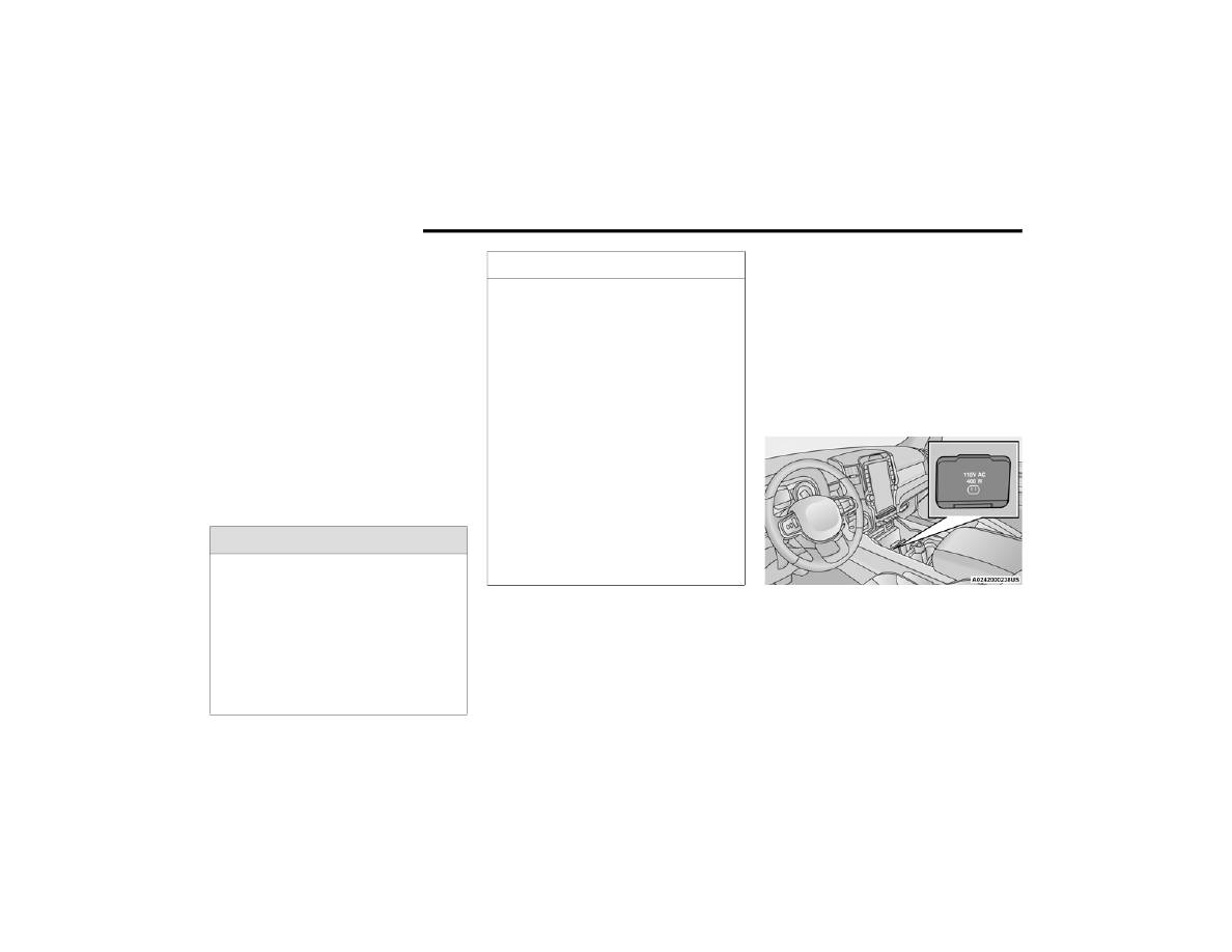
If equipped, there may be a 115 Volt (400 Watts 

Maximum) inverter located to the right of the 

center stack, just below the climate controls. 

This inverter can power cellular phones, 

electronics and other low power devices 

requiring power up to 400 Watts. Certain 

high-end video game consoles exceed this 

power limit, as will most power tools.

Center Stack Power Inverter

To turn on the power outlet, simply plug in the 

device. The outlet turns off when the device is 

unplugged.

NOTE:

The power inverter only turns on if the ignition 

is in the ACC or ON/RUN position.

Due to built-in overload protection, the power 

inverter shuts down if the power rating is 

exceeded.

WARNING!

To avoid serious injury or death:

Do not insert any objects into the receptacles.

Do not touch with wet hands.

Close the lid when not in use.

If this outlet is mishandled, it may cause an 

electric shock and failure.

2

-------------------------------------------------------------------------------------------------------------------------------------------------------------

76

GETTING TO KNOW YOUR VEHICLE


W

IRELESS

 C

HARGING

 P

AD

 — I

F


E

QUIPPED


Wireless Charging Pad

Your vehicle may be equipped with a 15W 3A Qi 

wireless charging pad located inside of the center 

console. This charging pad is designed to 

wirelessly charge your Qi enabled mobile phone. 

Qi is a standard that uses magnetic induction to 

transfer power to your mobile device.
Your mobile phone must be designed for Qi 

wireless charging. If the phone is not equipped 

with Qi wireless charging functionality, an 

aftermarket sleeve or a specialized back plate 

can be purchased from your mobile phone 

provider or a local electronics retailer. Please 

see your phone’s owner’s manual for further 

information.
The wireless charging pad is equipped with an 

anti-slip mat, an adjustable cradle to hold your 

mobile phone in place and an LED indicator light.

NOTE:

Using a phone case may interfere with wireless 

charging.

WINDOWS 

P

OWER

 W

INDOWS

 — I

F

 E

QUIPPED

The window controls on the driver's door control 

all the door windows.

Power Window Switches

The passenger door windows can also be 

operated by using the single window controls

on the passenger door trim panel. The window 

controls will operate only when the ignition is in 

the ACC or ON/RUN position.
To open the window part way (manually), push 

the window switch down briefly and release.

CAUTION!

The key fob should not be placed on the 

charging pad or within 15 cm (150 mm) of it. 

Doing so can cause excessive heat buildup 

and damage to the fob. Placing the fob in 

close proximity of the charging pad blocks the 

fob from being detected by the vehicle and 

prevents the vehicle from starting.

-------------------------------------------------------------------------------------------------------------------------------------------------------------

GETTING TO KNOW YOUR VEHICLE

77

NOTE:

The power window switches will remain active 

for up to 10 minutes after the ignition is placed 

in the OFF position. Opening either front door 

will cancel this feature. The timing is program

-

mable within Uconnect Settings  

Ú

page 228.

A

UTOMATIC

 W

INDOW

 F

EATURES

 — I

F


E

QUIPPED

Auto-Down Feature
The driver and front passenger door power 

window switches have an Auto-Down feature. 

Push the window switch down for a short period 

of time, then release, and the window will go 

down automatically.
To stop the window from going all the way down 

during the Auto-Down operation, pull up or push 

down on the switch briefly.
Auto-Up Feature With Anti-Pinch Protection
Lift the window switch up for a short period 

of time and release; the window will go up 

automatically.
To stop the window from going all the way up 

during the Auto-Up operation, push down on the 

switch briefly.
To close the window part way, lift the window 

switch briefly and release it when you want the 

window to stop.
If the window runs into any obstacle during 

auto-closure, it will reverse direction and then 

go back down. Remove the obstacle and use 

the window switch again to close the window.

NOTE:

Any impact due to rough road conditions may 

trigger the auto-reverse function unexpectedly 

during auto-closure. If this happens, pull the 

switch lightly and hold to close the window 

manually.

R

ESET

 A

UTO

-U

P


Should the Auto-Up feature stop working, the 

window probably needs to be reset. To reset 

Auto-Up:

1. Pull the window switch up to close the 

window completely and continue to hold 

the switch up for an additional two seconds 

after the window is closed.

2. Push the window switch down firmly to open 

the window completely and continue to hold 

the switch down for an additional two 

seconds after the window is fully open.

WARNING!

Never leave children unattended in a vehicle. 

Do not leave the key fob in or near the vehicle 

or in a location accessible to children, and do 

not leave the ignition of a vehicle equipped 

with Keyless Enter-N-Go in the ACC or 

ON/RUN mode. Occupants, particularly 

unattended children, can become entrapped 

by the windows while operating the power 

window switches. Such entrapment may 

result in serious injury or death.

WARNING!

There is no anti-pinch protection when the 

window is almost closed. To avoid personal 

injury be sure to clear your arms, hands, 

fingers and all objects from the window path 

before closing.

2

-------------------------------------------------------------------------------------------------------------------------------------------------------------

78

GETTING TO KNOW YOUR VEHICLE


W

INDOW

 L

OCKOUT

 S

WITCH

 — I

F


E

QUIPPED

The window lockout switch on the driver's door 

trim panel allows you to disable the window 

controls on the rear passenger doors. To disable 

the window controls, push and release the 

window lockout button (the indicator light on

the button will turn on). To enable the window 

controls, push and release the window lockout 

button again (the indicator light on the button will 

turn off).

Window Lockout Switch

P

OWER

 S

LIDING

 R

EAR

 W

INDOW

 — I

F


E

QUIPPED


The switch for the power sliding rear window 

is located on the overhead console. Push the 

switch rearward to open the glass. Pull the 

switch forward to close the glass.

Power Sliding Rear Window Switch

M

ANUAL

 S

LIDING

 R

EAR

 W

INDOW

 — I

F


E

QUIPPED

A locking device in the center of the window 

helps to prevent entry from the rear of the 

vehicle. Squeeze the lock to release the 

window.

W

IND

 B

UFFETING


Wind buffeting can be described as the 

perception of pressure on the ears or a 

helicopter-type sound in the ears. Your vehicle 

may exhibit wind buffeting with the windows 

down, or the sunroof (if equipped) in certain 

open or partially open positions. This is a 

normal occurrence and can be minimized. 

If the buffeting occurs with the rear windows 

open, open the front and rear windows together 

to minimize the buffeting. If the buffeting occurs 

with the sunroof open, adjust the sunroof 

opening to minimize the buffeting or open any 

window.

-------------------------------------------------------------------------------------------------------------------------------------------------------------

GETTING TO KNOW YOUR VEHICLE

79

HOOD    

T

O

 O

PEN

 T

HE

 H

OOD


To open the hood, two latches must be 

released.

1. Pull the hood release lever located below 

the steering wheel at the base of the 

instrument panel.

Hood Release

2. Reach into the opening beneath the center 

of the hood and push the safety latch lever 

to the left to release it, before raising the 

hood.

Safety Latch Location

T

O

 C

LOSE

 T

HE

 H

OOD

Hoods equipped with gas props are closed from 

the point where the props no longer hold the 

hood open.

WARNING!

Be sure the hood is fully latched before 

driving your vehicle. If the hood is not fully 

latched, it could open when the vehicle is in 

motion and block your vision. Failure to follow 

this warning could result in serious injury or 

death.

CAUTION!

To prevent possible damage, do not slam the 

hood to close it. Use a firm downward push at 

the front center of the hood to ensure that 

both latches engage.

2

-------------------------------------------------------------------------------------------------------------------------------------------------------------

80  

GETTING TO KNOW YOUR INSTRUMENT PANEL

BASE / MIDLINE INSTRUMENT CLUSTER — GASOLINE

Base / Midline Instrument Cluster — Gasoline

-------------------------------------------------------------------------------------------------------------------------------------------------------------

GETTING TO KNOW YOUR INSTRUMENT PANEL

81

B

ASE

 / M

IDLINE

 I

NSTRUMENT

 C

LUSTER


D

ESCRIPTIONS

1. Tachometer

Indicates the engine speed in revolutions 

per minute (RPM x 1000).

2. Voltmeter

When the vehicle is in the RUN state, the 

gauge indicates the electrical system 

voltage. The pointer should stay within 

the normal range if the battery is 

charged. If the pointer moves to either 

extreme left or right and remains there 

during normal driving, the electrical 

system should be serviced.

3. Instrument Cluster Display

When the appropriate conditions exist, 

this display shows the instrument cluster 

display messages  

Ú

page 90.

Base Instrument Cluster Display

The display always shows one of the main 

menu item after ignition on.

4. Oil Pressure Gauge

The pointer should always indicate the

oil pressure when the engine is running. 

A continuous high or low reading under 

normal driving conditions may indicate a 

lubrication system malfunction. Imme

-

diate service should be obtained from an 

authorized dealer.

5. Speedometer

Indicates vehicle speed.

1 – Instrument Cluster Display Controls
2 – Instrument Cluster Display Screen

3

-------------------------------------------------------------------------------------------------------------------------------------------------------------

82

GETTING TO KNOW YOUR INSTRUMENT PANEL


6. Temperature Gauge

The gauge pointer shows engine coolant 

temperature. The pointer positioned 

within the normal range indicates that 

the engine cooling system is operating 

satisfactorily.

The gauge pointer will likely indicate a 

higher temperature when driving in hot 

weather, up mountain grades, or when 

towing a trailer. It should not be allowed 

to exceed the upper limits of the normal 

operating range.

7. Fuel Gauge

The pointer shows the level of fuel in

the fuel tank when the ignition is in the 

ON/RUN position.

 The fuel pump symbol points 

to the side of the vehicle where 

the fuel door is located.

WARNING!

A hot engine cooling system is dangerous. 

You or others could be badly burned by steam 

or boiling coolant. It is recommended to call an 

authorized dealer for service if your vehicle 

overheats. If you decide to look under the hood 

yourself, Follow the warnings under the Cooling 

System Pressure Cap paragraph  

Ú

page 383.

CAUTION!

Driving with a hot engine cooling system could 

damage your vehicle. If the temperature gauge 

reads “H,” pull over and stop the vehicle. Idle 

the vehicle with the air conditioner turned off 

until the pointer drops back into the normal 

range. If the pointer remains on the “H,” turn 

the engine off immediately and call an 

authorized dealer for service.

-------------------------------------------------------------------------------------------------------------------------------------------------------------

GETTING TO KNOW YOUR INSTRUMENT PANEL

83

PREMIUM INSTRUMENT CLUSTER — GASOLINE

Premium Instrument Cluster — Gasoline

3

-------------------------------------------------------------------------------------------------------------------------------------------------------------

84

GETTING TO KNOW YOUR INSTRUMENT PANEL


P

REMIUM

 I

NSTRUMENT

 C

LUSTER


D

ESCRIPTIONS

1. Tachometer

Indicates the engine speed in revolutions 

per minute (RPM x 1000).

2. Instrument Cluster Display

When the appropriate conditions exist, 

this display shows the instrument cluster 

display messages  

Ú

page 90.

Premium Instrument Cluster Display

The display always shows one of the main 

menu item after ignition on.

3. Speedometer

Indicates vehicle speed.

4. Temperature Gauge

The gauge pointer shows engine coolant 

temperature. The pointer positioned 

within the normal range indicates that 

the engine cooling system is operating 

satisfactorily.

The gauge pointer will likely indicate a 

higher temperature when driving in hot 

weather, up mountain grades, or when 

towing a trailer. It should not be allowed 

to exceed the upper limits of the normal 

operating range.

5. Fuel Gauge

The pointer shows the level of fuel in

the fuel tank when the ignition is in the 

ON/RUN position.

 The fuel pump symbol points 

to the side of the vehicle where 

the fuel door is located.

1 – Instrument Cluster Display Controls
2 – Instrument Cluster Display Screen

WARNING!

A hot engine cooling system is dangerous. You or 

others could be badly burned by steam or boiling 

coolant. It is recommended to call an authorized 

dealer for service if your vehicle overheats. If you 

decide to look under the hood yourself, Follow the 

warnings under the Cooling System Pressure Cap 

paragraph  

Ú

page 383.

CAUTION!

Driving with a hot engine cooling system could 

damage your vehicle. If the temperature gauge 

reads “H,” pull over and stop the vehicle. Idle the 

vehicle with the air conditioner turned off until the 

pointer drops back into the normal range. If the 

pointer remains on the “H,” turn the engine off 

immediately and call an authorized dealer for 

service.

-------------------------------------------------------------------------------------------------------------------------------------------------------------

GETTING TO KNOW YOUR INSTRUMENT PANEL

85

BASE / MIDLINE INSTRUMENT CLUSTER — DIESEL

Base / Midline Diesel Instrument Cluster — Diesel

3

-------------------------------------------------------------------------------------------------------------------------------------------------------------

86

GETTING TO KNOW YOUR INSTRUMENT PANEL


D

IESEL

 I

NSTRUMENT

 C

LUSTER


1. Tachometer

Indicates the engine speed in revolutions 

per minute (RPM x 1000).

2. Engine Coolant Temperature

This gauge shows the engine coolant 

temperature. The gauge pointer will likely 

show higher temperatures when driving 

in hot weather, up mountain grades, or in 

heavy stop and go traffic. If the red 

Warning Light turns on while driving, 

safely bring the vehicle to a stop, and 

turn off the engine. DO NOT operate the 

vehicle until the cause is corrected.

3. Instrument Cluster Display

When the appropriate conditions exist, 

this display shows the instrument cluster 

display messages  

Ú

page 90.

Base Instrument Cluster Display

The display always shows one of the main 

menu item after ignition on.

WARNING!

A hot engine cooling system is dangerous. 

You or others could be badly burned by steam 

or boiling coolant. It is recommended to call 

an authorized dealer for service if your 

vehicle overheats.

CAUTION!

Driving with a hot engine cooling system could 

damage your vehicle. If the temperature gauge 

reads greater “H,” pull over and stop the 

vehicle. Idle the vehicle with the air conditioner 

turned off until the pointer drops back into the 

normal range. If the pointer remains on the 

“h,” turn the engine off immediately and call 

an authorized dealer for service.

1 – Instrument Cluster Display Controls
2 – Instrument Cluster Display Screen

-------------------------------------------------------------------------------------------------------------------------------------------------------------

GETTING TO KNOW YOUR INSTRUMENT PANEL

87

4. Oil Pressure Gauge

The pointer should always indicate some 

oil pressure when the engine is running. 

A continuous high or low reading under 

normal driving conditions may indicate a 

lubrication system malfunction. Imme

-

diate service should be obtained from an 

authorized dealer.

5. Speedometer

Indicates vehicle speed.

6. Diesel Exhaust Fluid (DEF) Gauge

The DEF Gauge displays the actual level of 

Diesel Exhaust Fluid in the DEF tank. DEF 

is required to maintain normal vehicle 

operation and emissions compliance. If 

something is wrong with the gauge, a DEF 

Warning Message or Malfunction Indicator 

Light (MIL) will be displayed. More informa

-

tion is available in the instrument cluster 

display section under the heading of DEF 

Warning Messages.

7. Fuel Gauge

The pointer shows the level of fuel in the 

fuel tank when the ignition switch is in 

the ON/RUN position.

 The fuel pump symbol points 

to the side of the vehicle where 

the fuel filler door is located.

NOTE:

The gauge may take up to five seconds to 

update after adding a gallon or more of DEF 

to the DEF tank. If you have a fault related to 

the DEF system, the gauge may not update to 

the new level. See an authorized dealer for 

service.

The DEF gauge may also not immediately 

update after a refill if the temperature of the 

DEF fluid is below 39°F (4°C). The DEF tank 

heater will possibly warm up the DEF fluid 

and allow the gauge to update after a period 

of run time. Under very cold conditions, it is 

possible that the gauge may not reflect the 

new fill level for several drives.

3

-------------------------------------------------------------------------------------------------------------------------------------------------------------

88

GETTING TO KNOW YOUR INSTRUMENT PANEL


PREMIUM INSTRUMENT CLUSTER — DIESEL 

Premium Instrument Cluster — Diesel

-------------------------------------------------------------------------------------------------------------------------------------------------------------

GETTING TO KNOW YOUR INSTRUMENT PANEL

89

D

IESEL

 I

NSTRUMENT

 C

LUSTER


1. Tachometer

Indicates the engine speed in revolutions 

per minute (RPM x 1000).

2. Instrument Cluster Display

When the appropriate conditions exist, 

this display shows the instrument cluster 

display messages  

Ú

page 90.

Premium Instrument Cluster Display

The display always shows one of the main 

menu item after ignition on.

3. Speedometer

Indicates vehicle speed.

4. Diesel Exhaust Fluid (DEF) Gauge

The DEF Gauge displays the actual level 

of Diesel Exhaust Fluid in the DEF tank. 

DEF is required to maintain normal 

vehicle operation and emissions compli

-

ance. If something is wrong with the 

gauge, a DEF Warning Message or 

Malfunction Indicator Light (MIL) will be 

displayed. More information is available 

in the instrument cluster display section 

under the heading of Diesel Exhaust 

Fluid (DEF) Warning Messages.

5. Fuel Gauge

The pointer shows the level of fuel in the 

fuel tank when the ignition switch is in 

the ON/RUN position.

 The fuel pump symbol points 

to the side of the vehicle where 

the fuel filler door is located.

NOTE:

The DEF tank on these vehicles is designed 

with a large amount of full reserve. So the 

level sensor will indicate a full reading even 

before the tank is completely full. To put it 

another way, there’s additional storage 

capacity in the tank above the Full mark 

that’s not represented in the gauge. You may 

not see any movement in the reading – even 

after driving up to 200 miles (321 kilome

-

ters) in some cases.

The gauge may take up to five seconds to 

update after adding a gallon or more of DEF 

to the DEF tank. If you have a fault related to 

the DEF system, the gauge may not update to 

the new level. See an authorized dealer for 

service.

The DEF gauge may also not immediately 

update after a refill if the temperature of the 

DEF fluid is below 39°F (4°C). The DEF tank 

heater will possibly warm up the DEF fluid 

and allow the gauge to update after a period 

of run time. Under very cold conditions, it is 

possible that the gauge may not reflect the 

new fill level for several drives.

1 – Instrument Cluster Display Controls
2 – Instrument Cluster Display Screen

3

-------------------------------------------------------------------------------------------------------------------------------------------------------------


Content      ..     3      4      5      6     ..