RAM 3500 Chassis Cab (2021 year). Manual in english - page 17
 

  Index      Manuals     RAM 3500 Chassis Cab (2021 year). Manual in english


Search            copyright infringement  


Content      ..     15      16      17      18     ..


RAM 3500 Chassis Cab (2021 year). Manual in english - page 17


266

MULTIMEDIA


Place/Retrieve A Call From Hold

During an active call, press the Hold or Call On 

Hold button on the Phone main screen.

Making A Second Call While Current Call Is In 

Progress

You can place a call on hold by pressing the 

Hold button on the Phone main screen, then 

dial a number from the keypad (if supported by 

your mobile phone), recent calls, SMS Inbox or 

from the phonebooks.

Toggling Between Calls

Uconnect 3 With 5-inch Display

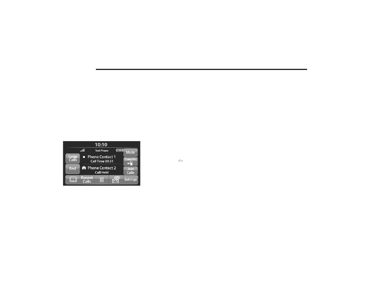
If two calls are in progress (one active and one 

on hold), press the Swap Calls button on the 

phone main screen. Only one call can be placed 

on hold at a time.

You can also push the Phone button to toggle 

between the active and held phone call.

Join Calls

When two calls are in progress (one active and 

one on hold), press the Join/Merge Calls button 

on the Phone main screen to combine all calls 

into a conference call.

Call Termination

To end a call in progress, momentarily press the 

End Call button on the touchscreen or the Phone 

End button on the steering wheel. Only the active 

call(s) will be terminated and if there is a call on 

hold, it will become the new active call.

Redial

Push the VR button   and after the “Listening” 

prompt and the following beep, say “Redial.”
The Uconnect Phone will call the last number 

that was dialed from your mobile phone.

Call Continuation

Call continuation is the progression of a phone 

call on the Uconnect Phone after the vehicle 

ignition has been switched to OFF.

NOTE:

The call will remain within the vehicle audio 

system until the phone becomes out of range 

for the Bluetooth® connection. It is recom

-

mended to press the Transfer button on the 

touchscreen when leaving the vehicle.

Advanced Phone Connectivity

Transfer Call To And From Mobile Phone

The Uconnect Phone allows ongoing calls to be 

transferred from your mobile phone without 

terminating the call. To transfer an ongoing call 

from your connected mobile phone to the 

Uconnect Phone or vice versa, press the 

Transfer button on the Phone main screen.

-------------------------------------------------------------------------------------------------------------------------------------------------------------

MULTIMEDIA

267

Things You Should Know About Uconnect 

Phone

Voice Command

For the best performance:

Always wait for the beep before speaking

Speak normally, without pausing, just as you 

would speak to a person sitting a few feet/

meters away from you

Ensure that no one other than you is 

speaking during a voice command period

Low-To-Medium Blower Setting

Low-To-Medium Vehicle Speed

Low Road Noise

Smooth Road Surface

Fully Closed Windows

Dry Weather Conditions

Even though the system is designed for many 

languages and accents, the system may not 

always work for some.

NOTE:

It is recommended that you do not store names 

in your Favorites phonebook while the vehicle is 

in motion.

Number and name recognition rate is optimized 

when the entries are not similar. You can say 

“O” (letter “O”) for “0” (zero).
Even though international dialing for most 

number combinations is supported, some 

shortcut dialing number combinations may not 

be supported.

Audio Performance
Audio quality is maximized under:

Low-To-Medium Blower Setting

Low-To-Medium Vehicle Speed

Low Road Noise

Smooth Road Surface

Fully Closed Windows

Dry Weather Conditions

Operation From The Driver's Seat

Performance such as audio clarity, echo, and 

loudness to a large degree rely on the phone 

and network, and not the Uconnect Phone.
Echo at the far end can sometimes be reduced 

by lowering the in-vehicle audio volume.
Phone Voice Commands
Making and answering hands-free phone calls 

is easy with Uconnect. When the Phonebook 

button is illuminated on your touchscreen, your 

system is ready. Check UconnectPhone.com

for mobile phone compatibility and pairing 

instructions.

WARNING!

ALWAYS drive safely with your hands on the 

wheel. You have full responsibility and 

assume all risks related to the use of the 

Uconnect features and applications in this 

vehicle. Only use Uconnect when it is safe

to do so. Failure to do so may result in an 

accident involving serious injury or death.

5

-------------------------------------------------------------------------------------------------------------------------------------------------------------

268

MULTIMEDIA


Push the Phone button   and wait for the beep 

to say a command. See some examples below:

“Call John Smith”

“Dial 123 456 7890”

“Redial” (call previous outgoing phone number)

“Call back” (call previously answered 

incoming phone number)

Did You Know: When providing a Voice 
Command, push the Phone button   and say 

“Call”, then pronounce the name exactly as it 

appears in your phonebook. When a contact 

has multiple phone numbers, you can say 

“Call John Smith work”.
Voice Text Reply — If Equipped
Uconnect can announce incoming text 
messages. Push the VR button   or Phone 
button   and say:

1. “Listen” to have the system read an 

incoming text message. (Must have 

compatible mobile phone paired to 

Uconnect system.)

2. “Reply” after an incoming text message has 

been read.
Listen to the Uconnect prompts. After the 

beep, repeat one of the predefined messag

-

es and follow the system prompts.

NOTE:

Only use the numbering listed in the provided 

table. Otherwise, the system will not transpose 

the message.

Did You Know: Your mobile phone must have the full 

implementation of the Message Access Profile 

(MAP) to take advantage of this feature. For details 

about MAP, visit UconnectPhone.com.
Apple® iPhone® iOS 6 or later supports reading 

incoming text messages only. For further 

information on how to enable this feature on 

your Apple® iPhone®, refer to your iPhone’s® 

“User Manual”.
Did You Know: Voice Text Reply is not 

compatible with iPhone®, but if your vehicle is 

equipped with Siri® Eyes Free, you can use your 

voice to send a text message.
Siri® Eyes Free — If Equipped
When used with your Apple® iPhone® connected 

to your vehicle via Bluetooth®, Siri lets you use 

your voice to send text messages, select media, 

place phone calls and much more. Siri uses your 

natural language to understand what you mean 

and responds back to confirm your requests. 

PRE-DEFINED VOICE TEXT REPLY 

RESPONSES

Yes.

Stuck in 

traffic.

See you later.

No.

Start without 

me.

I’ll be late.

Okay.

Where are 

you?

I will be 5 <or 

10, 15, 20, 

25, 30, 45, 

60> minutes 

late.

Call me.

Are you there 

yet?

I’ll call you 

later.

I need 

directions.

See you in 5 

<or 10, 15, 

20, 25, 30, 

45, 60> 

minutes.

I’m on my 

way.

Can’t talk 

right now.

I’m lost.

Thanks.

-------------------------------------------------------------------------------------------------------------------------------------------------------------

MULTIMEDIA

269

The system is designed to keep your eyes on the 

road and your hands on the wheel by letting Siri 

help you perform useful tasks.
To enable Siri, push and hold, then release the 

Uconnect Voice Recognition (VR) button on the 

steering wheel. After you hear a double beep, 

you can ask Siri to play podcasts and music, get 

directions, read text messages, and many other 

useful requests.

Bluetooth® Communication Link

Mobile phones may lose connection to the Uconnect 

Phone. When this happens, the connection can 

generally be re-established by restarting the mobile 

phone. Your mobile phone is recommended to 

remain in Bluetooth® ON mode.

Power-Up

After switching the ignition key from OFF to either 

the ON/RUN or ACC position, or after a language 

change, you must wait at least 15 seconds prior 

to using the system 

Ú

page 449.

RADIO OPERATION AND MOBILE PHONES  

Under certain conditions, the mobile phone being 

on in your vehicle can cause erratic or noisy 

performance from your radio. This condition may be 

lessened or eliminated by relocating the mobile 

phone antenna. This condition is not harmful to

the radio. If your radio performance does not 

satisfactorily “clear” by the repositioning of the 

antenna, it is recommended that the radio volume 

be turned down or off during mobile phone 

operation when not using Uconnect (if equipped).

R

EGULATORY

 A

ND

 S

AFETY


I

NFORMATION

USA/CANADA
Exposure to Radio Frequency Radiation
The radiated output power of the internal 

wireless radio is far below the FCC and IC radio 

frequency exposure limits. Nevertheless, the 

wireless radio will be used in such a manner 

that the radio is 8 in (20 cm) or further from the 

human body.

The internal wireless radio operates within 

guidelines found in radio frequency safety 

standards and recommendations, which reflect 

the consensus of the scientific community.
The radio manufacturer believes the internal 

wireless radio is safe for use by consumers. 

The level of energy emitted is far less than the 

electromagnetic energy emitted by wireless 

devices such as mobile phones. However, the 

use of wireless radios may be restricted in some 

situations or environments, such as aboard 

airplanes. If you are unsure of restrictions, you 

are encouraged to ask for authorization before 

turning on the wireless radio  

Ú

page 449.

5

-------------------------------------------------------------------------------------------------------------------------------------------------------------

270

MULTIMEDIA


OFF-ROAD PAGES — IF EQUIPPED

Your vehicle may be equipped with Off-Road 

Pages which display vehicle information related 

to the drivetrain, transfer case, and coolant/oil 

gauges.
To access Off-Road Pages, press the Apps 

button on the touchscreen, and then select 

Off-Road Pages.

Main Menu

O

FF

-R

OAD

 P

AGES

 S

TATUS

 B

AR

The Off-Road Pages Status Bar is located along 

the bottom of Off-Road Pages and is present in 

each of the three selectable page options. It 

provides information for the following items:

1. Transfer Case Status

2. Latitude/Longitude

3. Altitude of the vehicle

4. Status of Hill Descent Control and Speed in 

MPH (km/h)

Status Bar 2WD/4WD

1 — Uconnect Apps Button
2 — Off-Road Pages App

1 — Transfer Case Status
2 — Latitude/Longitude
3 — Altitude
4 — Hill Descent Control Status

-------------------------------------------------------------------------------------------------------------------------------------------------------------

MULTIMEDIA

271

V

EHICLE

 D

YNAMICS

The Vehicle Dynamics page displays 

information concerning the vehicle’s transfer 

case and steering angle.
The following information is displayed:

1. Status of Transfer Case

2. Status of Front Axles — If Equipped

3. Status of the Rear Axles

4. Steering angle in degrees

Drivetrain Menu 2WD/4WD

A

CCESSORY

 G

AUGE

The Accessory Gauge page displays the current 

status of the vehicle’s Coolant Temperature, Oil 

Temperature, Oil Pressure, Transmission 

Temperature, and Battery Voltage.

Accessory Gauge Menu 2WD/4WD

1 — Transfer Case Status
2 — Front Axle Locker Status
3 — Steering Angle
4 — Rear Axle Locker Status

1 — Coolant Temperature
2 — Oil Temperature
3 — Oil Pressure
4 — Transmission Temperature
5 — Battery Voltage

5

-------------------------------------------------------------------------------------------------------------------------------------------------------------

272

MULTIMEDIA


P

ITCH

 & R

OLL

The Pitch & Roll page displays the vehicle’s 

current pitch (angle up and down) and roll 

(angle side to side) in degrees.The Pitch & Roll 

gauge provide a visualization of the current 

vehicle angle.

Pitch & Roll Menu 2WD/4WD

F

ORWARD

 F

ACING

 C

AMERA

Your vehicle may be equipped with a Forward 

Facing Camera that allows you to see an 

on-screen image of the front view of your 

vehicle. The image will be displayed on the 

touchscreen along with a caution note “Check 

Entire Surroundings” across the top of the 

screen.
To activate, press the Forward Facing Camera 

button on the touchscreen.

Forward Facing Camera Button

1 — Current Pitch
2 — Current Roll

-------------------------------------------------------------------------------------------------------------------------------------------------------------

273

(Continued)

SAFETY

SAFETY FEATURES

A

NTI

-L

OCK

 B

RAKE

 S

YSTEM

 (ABS) 

The ABS provides increased vehicle stability 

and brake performance under most braking 

conditions. The system automatically prevents 

wheel lock, and enhances vehicle control during 

braking.
The ABS performs a self-check cycle to ensure 

that the ABS is working properly each time the 

vehicle is started and driven. During this 

self-check, you may hear a slight clicking sound 

as well as some related motor noises.
ABS is activated during braking when the 

system detects one or more wheels are 

beginning to lock. Road conditions such as ice, 

snow, gravel, bumps, railroad tracks, loose 

debris, or panic stops may increase the 

likelihood of ABS activation(s).

You also may experience the following normal 

characteristics when ABS activates:

The ABS motor noise or clicking sounds (you 

may continue to hear for a short time after 

the stop)

Brake pedal pulsations

A slight drop of the brake pedal at the end of 

the stop

ABS is designed to function with the Original 

Equipment Manufacturer (OEM) tires. Modification 

may result in degraded ABS performance.

WARNING!

The ABS contains sophisticated electronic 

equipment that may be susceptible to inter

-

ference caused by improperly installed or 

high output radio transmitting equipment. 

This interference can cause possible loss of 

anti-lock braking capability. Installation of 

such equipment should be performed by 

qualified professionals.

Pumping of the Anti-Lock Brakes will diminish 

their effectiveness and may lead to a collision. 

Pumping makes the stopping distance longer. 

Just press firmly on your brake pedal when you 

need to slow down or stop.

The ABS cannot prevent the natural laws of 

physics from acting on the vehicle, nor can 

it increase braking or steering efficiency 

beyond that afforded by the condition of the 

vehicle brakes and tires or the traction 

afforded.

The ABS cannot prevent collisions, 

including those resulting from excessive 

speed in turns, following another vehicle 

too closely, or hydroplaning.

The capabilities of an ABS equipped vehicle 

must never be exploited in a reckless or 

dangerous manner that could jeopardize 

the user’s safety or the safety of others.

WARNING!

 (Continued)

6

-------------------------------------------------------------------------------------------------------------------------------------------------------------

274

SAFETY


Anti-Lock Brake System (ABS) Warning 

Light

The yellow ABS Warning Light will turn on when 

the ignition is placed in the ON/RUN mode and 

may stay on for as long as four seconds.
If the ABS Warning Light remains on or comes 

on while driving, it indicates that the anti-lock 

portion of the brake system is not functioning 

and that service is required. However, the 

conventional brake system will continue to 

operate normally if the ABS Warning Light is on.
If the ABS Warning Light is on, the brake system 

should be serviced as soon as possible to 

restore the benefits of Anti-Lock brakes. If the 

ABS Warning Light does not come on when the 

ignition is placed in the ON/RUN mode, have 

the light repaired as soon as possible.

E

LECTRONIC

 B

RAKE

 C

ONTROL

 (EBC) 

S

YSTEM


Your vehicle is equipped with an advanced 

Electronic Brake Control (EBC) system. This 

system includes Anti-Lock Brake System (ABS), 

Brake Assist System (BAS), Electronic Brake 

Force Distribution (EBD), Hill Start Assist (HSA), 

Electronic Roll Mitigation (ERM), Electronic 

Stability Control (ESC), and Traction Control 

System (TCS). These systems work together to 

enhance both vehicle stability and control in 

various driving conditions.
Your vehicle may also be equipped with Trailer 

Sway Control (TSC) and Hill Descent Control 

(HDC).

Brake Assist System (BAS) 

The BAS is designed to optimize the vehicle’s 

braking capability during emergency braking 

maneuvers. The system detects an emergency 

braking situation by sensing the rate and amount 

of brake application and then applies optimum 

pressure to the brakes. This can help reduce 

braking distances. The BAS complements the 

Anti-Lock Brake System (ABS). Applying the 

brakes very quickly results in the best BAS 

assistance. To receive the benefit of the system, 

you must apply continuous braking pressure 

during the stopping sequence (do not “pump” the 

brakes). Do not reduce brake pedal pressure 

unless braking is no longer desired. Once the 

brake pedal is released, the BAS is deactivated.

Brake System Warning Light

The red Brake System Warning Light will turn on 

when the ignition is placed in the ON/RUN mode 

and may stay on for as long as four seconds.
If the Brake System Warning Light remains on or 

comes on while driving, it indicates that the 

brake system is not functioning properly and 

that immediate service is required. If the Brake 

System Warning Light does not come on when 

the ignition is placed in the ON/RUN mode, 

have the light repaired as soon as possible.

WARNING!

The Brake Assist System (BAS) cannot prevent 

the natural laws of physics from acting on 

the vehicle, nor can it increase the traction 

afforded by prevailing road conditions. 

BAS cannot prevent collisions, including those 

resulting from excessive speed in turns, driving 

on very slippery surfaces, or hydroplaning. 

The capabilities of a BAS-equipped vehicle 

must never be exploited in a reckless or 

dangerous manner, which could jeopardize 

the user's safety or the safety of others.

-------------------------------------------------------------------------------------------------------------------------------------------------------------

SAFETY

275

Electronic Brake Force Distribution (EBD)

EBD manages the distribution of the braking 

torque between the front and rear axles by 

limiting braking pressure to the rear axle. This is 

done to prevent overslip of the rear wheels to 

avoid vehicle instability, and to prevent the rear 

axle from entering ABS before the front axle.

Electronic Roll Mitigation (ERM) 

ERM anticipates the potential for wheel lift by 

monitoring the driver’s steering wheel input and 

the speed of the vehicle. When ERM determines 

that the rate of change of the steering wheel 

angle and vehicle’s speed are sufficient to 

potentially cause wheel lift, it then applies the 

appropriate brake and may also reduce engine 

power to lessen the chance that wheel lift will 

occur. ERM can only reduce the chance of 

wheel lift occurring during severe or evasive 

driving maneuvers; it cannot prevent wheel lift 

due to other factors, such as road conditions, 

leaving the roadway, or striking objects or other 

vehicles.

NOTE:

ERM is disabled any time the ESC is in “Full Off” 

mode (if equipped). For a complete explanation 

of the available ESC modes, see  

Ú

page 275.

Electronic Stability Control (ESC) 

ESC enhances directional control and stability 

of the vehicle under various driving conditions. 

ESC corrects for oversteering or understeering 

of the vehicle by applying the brake of the 

appropriate wheel(s) to counteract the above 

conditions. Engine power may also be reduced 

to help the vehicle maintain the desired path.

Oversteer — when the vehicle is turning more 

than appropriate for the steering wheel position.

Understeer — when the vehicle is turning less 

than appropriate for the steering wheel position.

ESC uses sensors in the vehicle to determine 

the vehicle path intended by the driver and 

compares it to the actual path of the vehicle. 

When the actual path does not match the 

intended path, ESC applies the brake of the 

appropriate wheel to assist in counteracting the 

oversteer or understeer condition.
The ESC Activation/Malfunction Indicator Light 

located in the instrument cluster will start to flash 

as soon as the ESC system becomes active.

The ESC Activation/Malfunction Indicator Light 

also flashes when the TCS is active. If the ESC 

Activation/Malfunction Indicator Light begins to 

flash during acceleration, ease up on the 

accelerator and apply as little throttle as possible. 

Be sure to adapt your speed and driving to the 

prevailing road conditions.

WARNING!

Many factors, such as vehicle loading, road 

conditions and driving conditions, influence 

the chance that wheel lift or rollover may occur. 

ERM cannot prevent all wheel lift or roll overs, 

especially those that involve leaving the 

roadway or striking objects or other vehicles. 

The capabilities of an ERM-equipped vehicle 

must never be exploited in a reckless or 

dangerous manner which could jeopardize

the user's safety or the safety of others.

6

-------------------------------------------------------------------------------------------------------------------------------------------------------------

276

SAFETY


(Continued)

ESC Operating Modes

Depending upon model and mode of operation, the 

ESC system may have multiple operating modes.
ESC On
This is the normal operating mode for the ESC 

system. Whenever the vehicle is started, the ESC 

system will be in this mode. This mode should be 

used for most driving conditions. Alternate ESC 

modes should only be used for specific reasons 

as noted in the following paragraphs.
Partial Off
This mode may be useful if the vehicle becomes 

stuck. This mode may modify TCS and ESC 

thresholds for activation, which allows for more 

wheel spin than normally allowed.
To enter the “Partial Off” mode, momentarily 

push the ESC OFF button and the ESC OFF 

Indicator Light will illuminate. To turn the ESC 

on again, momentarily push the ESC OFF button 

and the ESC OFF Indicator Light will turn off.

WARNING!

Electronic Stability Control (ESC) cannot 

prevent the natural laws of physics from acting 

on the vehicle, nor can it increase the traction 

afforded by prevailing road conditions. ESC 

cannot prevent accidents, including those 

resulting from excessive speed in turns, driving 

on very slippery surfaces, or hydroplaning. ESC 

also cannot prevent accidents resulting from 

loss of vehicle control due to inappropriate 

driver input for the conditions. Only a safe, 

attentive, and skillful driver can prevent acci

-

dents. The capabilities of an ESC equipped 

vehicle must never be exploited in a reckless or 

dangerous manner which could jeopardize the 

user’s safety or the safety of others.

Vehicle modifications, or failure to properly 

maintain your vehicle, may change the 

handling characteristics of your vehicle, and 

may negatively affect the performance of the 

ESC system. Changes to the steering system, 

suspension, braking system, tire type and size 

or wheel size may adversely affect ESC perfor

-

mance. Improperly inflated and unevenly worn 

tires may also degrade ESC performance. 

Any vehicle modification or poor vehicle main

-

tenance that reduces the effectiveness of the 

ESC system can increase the risk of loss of 

vehicle control, vehicle rollover, personal injury 

and death.

WARNING!

 (Continued)

-------------------------------------------------------------------------------------------------------------------------------------------------------------

SAFETY

277

(Continued)

NOTE:

For vehicles with multiple partial ESC modes, 

the push and release of the button will toggle 

the ESC modes. Multiple attempts may be 

required to return to "ESC On" mode.

Full Off — If Equipped
This mode is intended for off-highway or 

off-road use only and should not be used on any 

public roadways. In this mode, TCS and ESC 

features are turned off. To enter the “Full Off” 

mode, push and hold the ESC OFF button for 

five seconds while the vehicle is stopped with 

the engine running. After five seconds, a chime 

will sound, the ESC OFF Indicator Light will 

illuminate, and the “ESC OFF” message will 

display in the instrument cluster. To turn ESC on 

again, momentarily push the ESC OFF button.

NOTE:

System may switch from ESC “Full Off” to 

“Partial Off” mode when vehicle exceeds a 

predetermined speed. When the vehicle speed 

slows below the predetermined speed the 

system will return to ESC “Full Off”.

ESC modes may also be affected by drive 

modes (if equipped).

ESC Activation/Malfunction Indicator Light 

And ESC OFF Indicator Light 

The ESC Activation/Malfunction Indicator 

Light in the instrument cluster will come 

on when the ignition is placed in the ON 

mode. It should go out with the engine 

running. If the ESC Activation/Malfunction Indicator 

Light comes on continuously with the engine 

running, a malfunction has been detected in the 

ESC system. If this light remains on after several 

ignition cycles, and the vehicle has been driven 

several miles (kilometers) at speeds greater than 

30 mph (48 km/h), see an authorized dealer as 

soon as possible to have the problem diagnosed 

and corrected.

WARNING!

When in “Partial Off” mode, the TCS function

-

ality of ESC, except for the limited slip 

feature described in the TCS section, has 

been disabled and the ESC OFF Indicator 

Light will be illuminated. When in “Partial 

Off” mode, the engine power reduction 

feature of TCS is disabled, and the enhanced 

vehicle stability offered by the ESC system is 

reduced.

Trailer Sway Control (TSC) is disabled when 

the ESC system is in the “Partial Off” mode.

WARNING!

In the ESC “Full Off” mode, the engine 

torque reduction and stability features are 

disabled. Therefore, enhanced vehicle 

stability offered by the ESC system is 

unavailable. In an emergency evasive 

maneuver, the ESC system will not engage 

to assist in maintaining stability. ESC “Full 

Off” mode is intended for off-highway or 

off-road use only.

The Electronic Stability Control (ESC) 

cannot prevent the natural laws of physics 

from acting on the vehicle, nor can it 

increase the traction afforded by prevailing 

road conditions. ESC cannot prevent all 

accidents, including those resulting from 

excessive speed in turns, driving on very 

slippery surfaces, or hydroplaning. ESC also 

cannot prevent collisions.

WARNING!

 (Continued)

6

-------------------------------------------------------------------------------------------------------------------------------------------------------------

278

SAFETY


The ESC Activation/Malfunction Indicator Light 

starts to flash as soon as the tires lose traction 

and the ESC system becomes active. The ESC 

Activation/Malfunction Indicator Light also 

flashes when TCS is active. If the ESC Activation/

Malfunction Indicator Light begins to flash during 

acceleration, ease up on the accelerator and 

apply as little throttle as possible. Be sure to 

adapt your speed and driving to the prevailing 

road conditions.

The ESC OFF Indicator Light indicates 

that the Electronic Stability Control 

(ESC) is in a reduced mode.

NOTE:

The ESC Activation/Malfunction Indicator 

Light and the ESC OFF Indicator Light come 

on momentarily each time the ignition is 

placed in the ON position.

Each time the ignition is placed in the ON 

position, the ESC system will be on even if it 

was turned off previously.

The ESC system will make buzzing or clicking 

sounds when it is active. This is normal; the 

sounds will stop when ESC becomes inactive 

following the maneuver that caused the ESC 

activation.

Hill Descent Control (HDC) — If Equipped  

HDC is intended for low speed off-road driving 

while in 4WD Low. HDC maintains vehicle speed 

while descending hills during various driving 

situations. HDC controls vehicle speed by 

actively controlling the brakes.
HDC Has Three States:

1. Off (feature is not enabled and will not 

activate).

2. Enabled (feature is enabled and ready but 

activation conditions are not met, or driver 

is actively overriding with brake or throttle 

application).

3. Active (feature is enabled and actively 

controlling vehicle speed).

Enabling HDC
HDC is enabled by pushing the HDC switch, but 

the following conditions must also be met to 

enable HDC:

The driveline is in 4WD Low.

The vehicle speed is below 5 mph (8 km/h).

The parking brake is released.

The driver door is closed.

Activating HDC
Once HDC is enabled it will activate 

automatically if driven down a grade of 

sufficient magnitude. The set speed for HDC is 

selectable by the driver, and can be adjusted by 

using the gear shift +/-. The following 

summarizes the HDC set speeds:
HDC Target Set Speeds

P = No set speed. HDC may be enabled but 

will not activate.

R = 0.6 mph (1 km/h)

N = 1.2 mph (2 km/h)

D = 0.6 mph (1 km/h)

1st = 0.6 mph (1 km/h)

2nd = 1.2 mph (2 km/h)

3rd = 1.8 mph (3 km/h)

4th = 2.5 mph (4 km/h)

5th = 3.1 mph (5 km/h)

6th = 3.7 mph (6 km/h)

7th = 4.3 mph (7 km/h)

-------------------------------------------------------------------------------------------------------------------------------------------------------------

SAFETY

279

8th = 5.0 mph (8 km/h)

9th = 5.6 mph (9 km/h) – If Equipped

NOTE:

During HDC the +/- shifter input is used for HDC 

target speed selection, but will not affect the 

gear chosen by the transmission. When actively 

controlling HDC the transmission will shift 

appropriately for the driver-selected set speed 

and corresponding driving conditions.

Driver Override
The driver may override HDC activation with 

throttle or brake application at any time.
Deactivating HDC
HDC will be deactivated but remain available if 

any of the following conditions occur:

Driver overrides HDC set speed with throttle 

or brake application.

Vehicle speed exceeds 20 mph (32 km/h) 

but remains below 40 mph (64 km/h).

Vehicle is on a downhill grade of insufficient 

magnitude, is on level ground, or is on an uphill 

grade.

Vehicle is shifted to PARK.

Disabling HDC
HDC will be deactivated and disabled if any of 

the following conditions occur:

The driver pushes the HDC switch.

The driveline is shifted out of 4WD Low.

The parking brake is applied.

The driver door opens.

The vehicle is driven greater than 20 mph 

(32 km/h) for greater than 70 seconds.

The vehicle is driven greater than 40 mph 

(64 km/h) (HDC exits immediately).

HDC detects excessive brake temperature.

Feedback To The Driver
The instrument cluster has an HDC icon and the 

HDC switch has an LED icon, which offers 

feedback to the driver about the state HDC is in.

The cluster icon and switch lamp will illumi

-

nate and remain on solid when HDC is 

enabled or activated. This is the normal oper

-

ating condition for HDC.

The cluster icon and switch lamp will flash for 

several seconds then extinguish when the 

driver pushes the HDC switch but enable 

conditions are not met.

The cluster icon and switch lamp will flash for 

several seconds then extinguish when HDC 

disables due to excess speed.

The cluster icon and switch lamp will flash 

when HDC deactivates due to overheated 

brakes. The flashing will stop and HDC will 

activate again once the brakes have cooled 

sufficiently.

WARNING!

HDC is only intended to assist the driver in 

controlling vehicle speed when descending 

hills. The driver must remain attentive to the 

driving conditions and is responsible for 

maintaining a safe vehicle speed.

6

-------------------------------------------------------------------------------------------------------------------------------------------------------------

280

SAFETY


(Continued)

Hill Start Assist (HSA)  

HSA is designed to mitigate roll back from a 

complete stop while on an incline. If the driver 

releases the brake while stopped on an incline, 

HSA will continue to hold the brake pressure for 

a short period. If the driver does not apply the 

throttle before this time expires, the system will 

release brake pressure and the vehicle will roll 

down the hill as normal.
The following conditions must be met in order 

for HSA to activate:

The feature must be enabled.

The vehicle must be stopped.

The parking brake must be off.

The driver door must be closed.

The vehicle must be on a sufficient grade.

The gear selection must match vehicle uphill 

direction (i.e., vehicle facing uphill is in 

forward gear; vehicle backing uphill is in 

REVERSE gear).

HSA will work in REVERSE gear and all forward 

gears. The system will not activate if the trans

-

mission is in PARK or NEUTRAL. For vehicles 

equipped with a manual transmission, if the 

clutch is pressed, HSA will remain active.

Disabling And Enabling HSA

This feature can be turned on or turned off. To 

change the current setting, proceed as follows:

If disabling HSA using your instrument cluster 

display, see  

Ú

page 90 for further information.

If disabling HSA using Uconnect Settings, see  

Ú

page 228 for further information.

Towing With HSA

HSA will also provide assistance to mitigate roll 

back while towing a trailer.

WARNING!

There may be situations where the Hill Start 

Assist (HSA) will not activate and slight rolling 

may occur, such as on minor hills or with a 

loaded vehicle, or while pulling a trailer. HSA is 

not a substitute for active driving involvement. 

It is always the driver’s responsibility to be 

attentive to distance to other vehicles, people, 

and objects, and most importantly brake 

operation to ensure safe operation of the 

vehicle under all road conditions. Your 

complete attention is always required while 

driving to maintain safe control of your vehicle. 

Failure to follow these warnings can result in a 

collision or serious personal injury.

WARNING!

If you use a trailer brake controller with your 

trailer, the trailer brakes may be activated 

and deactivated with the brake switch. If so, 

there may not be enough brake pressure to 

hold both the vehicle and the trailer on a hill 

when the brake pedal is released. In order to 

avoid rolling down an incline while resuming 

acceleration, manually activate the trailer 

brake or apply more vehicle brake pressure 

prior to releasing the brake pedal.

-------------------------------------------------------------------------------------------------------------------------------------------------------------

SAFETY

281

Traction Control System (TCS) 

TCS monitors the amount of wheel spin of each 

of the driven wheels. If wheel spin is detected, 

the TCS may apply brake pressure to the 

spinning wheel(s) and/or reduce engine power 

to provide enhanced acceleration and stability. 

A feature of the TCS, Brake Limited Differential 

(BLD), functions similarly to a limited slip 

differential and controls the wheel spin across a 

driven axle. If one wheel on a driven axle is 

spinning faster than the other, the system will 

apply the brake of the spinning wheel. This will 

allow more engine power to be applied to the 

wheel that is not spinning. BLD may remain 

enabled even if TCS and Electronic Stability 

Control (ESC) are in reduced modes.

Trailer Sway Control (TSC)  

TSC uses sensors in the vehicle to recognize an 

excessively swaying trailer and will take the 

appropriate actions to attempt to stop the sway.

NOTE:

TSC cannot stop all trailers from swaying. 

Always use caution when towing a trailer and 

follow the trailer tongue weight recommenda

-

tions  

Ú

page 200.

When TSC is functioning, the ESC Activation/

Malfunction Indicator Light will flash, the engine 

power may be reduced and you may feel the 

brakes being applied to individual wheels to 

attempt to stop the trailer from swaying. TSC is 

disabled when the ESC system is in the “Partial 

Off” or “Full Off” modes.

AUXILIARY DRIVING SYSTEMS

F

ORWARD

 C

OLLISION

 W

ARNING

 (FCW) 

W

ITH

 M

ITIGATION

 — I

F

 E

QUIPPED

FCW with Mitigation provides the driver with 

audible warnings, visual warnings (within the 

instrument cluster display), and may apply a 

brake jerk to warn the driver when it detects a 

potential frontal collision. The warnings and 

limited braking are intended to provide the 

driver with enough time to react, avoid or 

mitigate the potential collision.

NOTE:

FCW monitors the information from the forward 

looking sensors as well as the Electronic Brake 

Controller (EBC), to calculate the probability of a 

forward collision. When the system determines 

that a forward collision is probable, the driver 

will be provided with audible and visual warn

-

ings as well as a possible brake jerk warning. 

If the driver does not take action based upon 

these progressive warnings, then the system 

will provide a limited level of active braking to 

help slow the vehicle and mitigate the potential 

forward collision. If the driver reacts to the warn

-

ings by braking and the system determines that 

HSA is not a parking brake. Always apply 

the parking brake fully when exiting your 

vehicle. Also, be certain to place the trans

-

mission in PARK.

Failure to follow these warnings can result 

in a collision or serious personal injury.

WARNING!

 (Continued)

WARNING!

If TSC activates while driving, slow the vehicle 

down, stop at the nearest safe location, and 

adjust the trailer load to eliminate trailer 

sway.

6

-------------------------------------------------------------------------------------------------------------------------------------------------------------


Content      ..     15      16      17      18     ..