Acura RSX Honda Integra. Manual - part 475
01
01
S6M6A00K79100081011FAAT20
−
−
−
−
DTC 1-1:
Special Tools Required
YES
NO
YES
NO
23-32
SRS
DTC Troubleshooting
A
07XAZ-SZ30100
07SAZ-TB4011A
A
Open or Increased Resistance in
Driver’s Airbag Inflator
• SRS inflator simulator 07SAZ-TB4011A
• SRS simulator lead F 07XAZ-SZ30100
1. Erase the DTC memory (see page 23-23).
2. Turn the ignition switch ON (II), and check that the
SRS indicator comes on for about 6 seconds and
then goes off.
Go to step 3.
Intermittent failure, system is OK at this time.
Go to Troubleshooting Intermittent Failures
(see page 23-24). If another DTC is indicated, go to
the DTC Troubleshooting Index.
3. Turn the ignition switch OFF. Disconnect the
battery negative cable, and wait for 3 minutes.
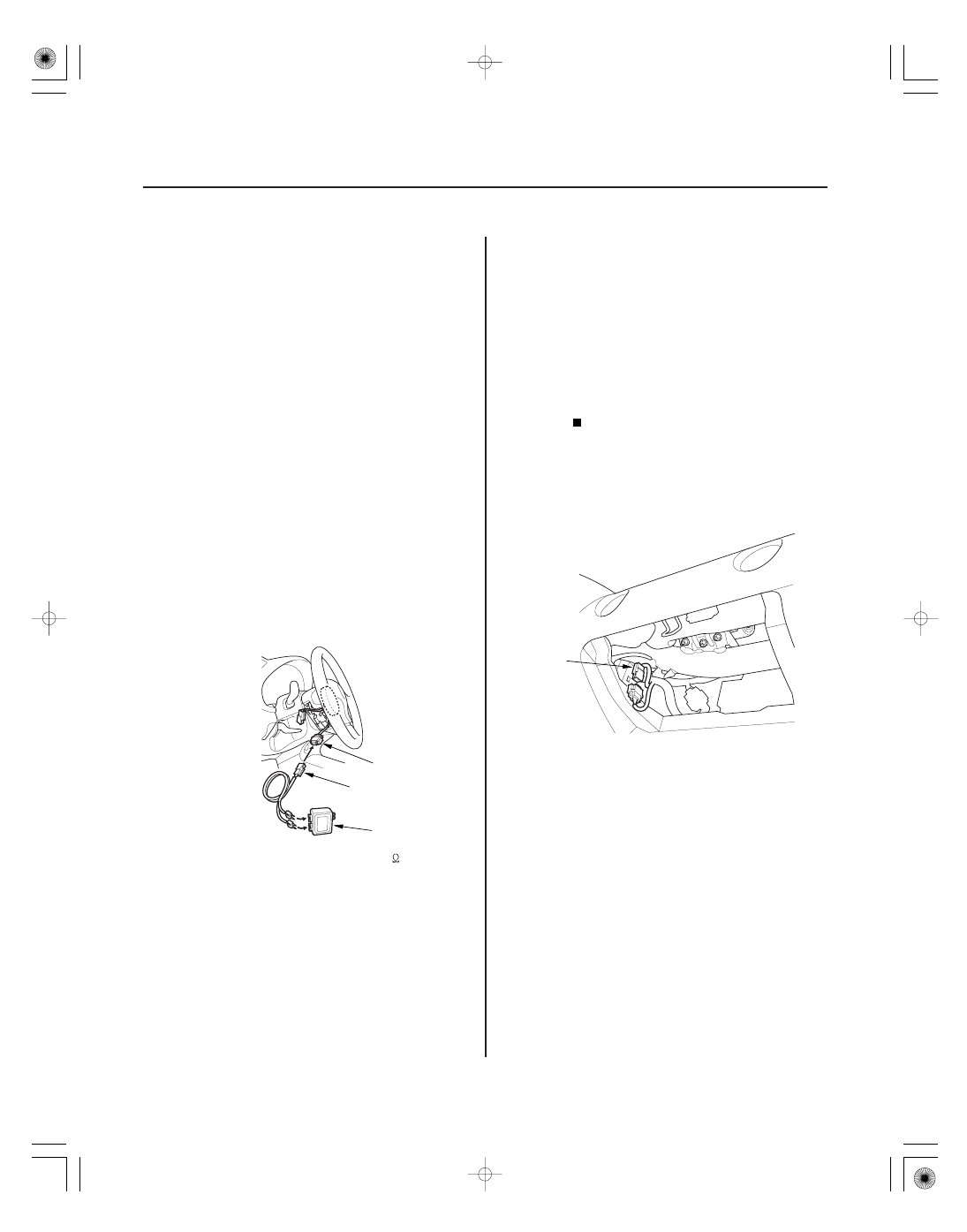
4. Disconnect the driver’s airbag 4P connector from
the cable reel (A).
5. Connect the SRS inflator simulator (2
connectors) and the simulator lead F to the cable
reel 4P connector.
6. Reconnect the battery negative cable.
7. Erase the DTC memory.
8. Read the DTC.
Go to step 9.
Open or increased resistance in the driver’s
airbag inflator; replace the driver’s airbag (see page
23-130).
9. Turn the ignition switch OFF. Disconnect the
battery negative cable, and wait for 3 minutes.
10. Disconnect the front passenger’s airbag 4P
connector (A) from the dashboard wire harness.
Does the SRS indicator stay on?
Is DT C 1-1 indicated?
05/06/27 18:08:43 61S6M040_230_0032