Acura RSX Honda Integra. Manual - part 193


  Index      Acura     Acura RSX Honda Integra - service repair manual 2002-2006 year


Search            


Content   ..  191  192  193  194   ..


Acura RSX Honda Integra. Manual - part 193


*01

S6M6A01E34116300000DAAT00

12-3

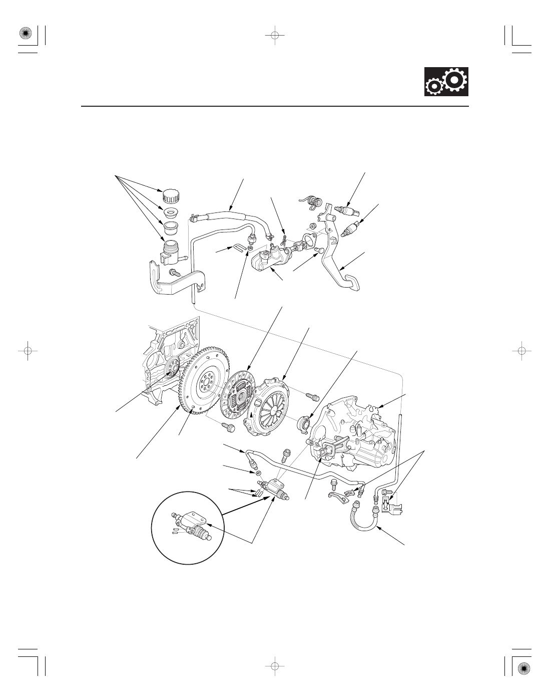
Component Location Index

RESERVOIR

RESERVOIR HOSE

LOCK PIN

CLUTCH INTERLOCK SWITCH

CLUTCH PEDAL

CLUTCH PEDAL POSITION
SWITCH

PEDAL PIN

RETAINING
CLIP

CLUTCH DISK

PRESSURE PLATE

RELEASE BEARING

M/T ASSEMBLY

CLUTCH
HOSE CLIP

CLUTCH HOSE

RELEASE FOLK

SLAVE CYLINDER

O-RING

ROLL PIN

DOWEL PIN

CLUTCH LINE

FLYWHEEL

PILOT BUSHING

O-RING

CLUTCH MASTER CYLINDER

2005-2006 6-speed models

Replace.

Adjustment,

page 12-6

Adjust ment,

page 12-6

Adjustment, page 12-6

Replace.

Removal, page 12-12
Replacement, page 12-15

Removal, page 12-12
Installation, page 12-15

Replacement, page 12-16

Replacement, page 12-9

Replace.

Inspection, page 12-14
Replacement, page 12-14

Installation,

page 7-26

Replace.

Replacement,

page 12-7

05/06/27 18:07:54 61S6M040_120_0005

01

S6M6A13E34116300000CAAT00

Delay Orifice Mechanism (2005-2006 6-speed models)

Function

12-4

Clutch

System Description

DELAY ORIFICE MECHANISM

The delay orifice mechanism improves clutch operation by delaying the slave cylinder release speed when the clutch
pedal is suddenly released. The delay orifice mechanism is built into the slave cylinder.

05/06/27 18:07:54 61S6M040_120_0006

02

03

Operation

12-5

FILTER PART

ORIFICE PART

To SLAVE CYLINDER

ONE-WAY VALVE

From
MASTER CYLINDER

FILTER PART

ORIFICE PART

From SLAVE CYLINDER

ONE-WAY VALVE

To
MASTER CYLINDER

When the clutch pedal is pressed, the fluid pressure from the master cylinder moves the one-way valve in the
direction shown in the illustration. The fluid flows through two passages: the orifice part and the filter part. It then
flows out to the slave cylinder to release the pressure plate and clutch disc joint.

When the clutch pedal is released, the fluid pressure from the slave cylinder moves the one-way valve in the direction
shown in the illustration. The one-way valve blocks the filter-part passage and delays the clutch release speed by
returning the fluid to the master cylinder through only the orifice-part passage.

05/06/27 18:07:55 61S6M040_120_0007

*01

S6M6A01E34116317041MBAT20

Clutch Pedal Stroke:

130

140 mm (5.12

5.51 in.)

Clutch Pedal Free Play:

10

16 mm (0.39

0.63 in.)

Clutch Pedal Height:

197 mm (7.76 in.)

Clutch Pedal Disengement Height:

115 mm (4.53 in.)

12-6

Clutch

Clutch Pedal, Clutch Pedal Position Switch, and Clutch Interlock Switch
Adjustment

J
9.8 N·m
(1.0 kgf·m, 7.2 lbf·ft)

B

C

D
17 N·m
(1.7 kgf·m,
12 lbf·ft)

F

G

H

I

K

A
9.8 N·m
(1.0 kgf·m, 7.2 lbf·ft)

E

NOTE:

• Check the clutch pedal position switch (see page 4-71).
• Check the clutch interlock switch (see page 4-8).
• Remove the driver’s floor mat before adjusting the

clutch pedal.

• The clutch is self-adjusting to compensate for wear.
• If there is no clearance between the master cylinder

piston and pushrod, the release bearing will be held
against the diaphragm spring, which can result in
clutch slippage or other clutch problems.

1. Loosen the clutch pedal position switch locknut (A),

and back off the clutch pedal position switch (B) (or
adjusting bolt; without cruise control model) until it
no longer touches the clutch pedal (C).

2. Loosen the clutch pushrod locknut (D), and turn the

pushrod (E) in or out to get the specified height (F),
stroke (G), free play (H) and disengement height (I)
at the clutch pedal.

3. Tighten the clutch pushrod locknut.

4. With the clutch pedal released, turn in the clutch

pedal position switch until it contacts the clutch
pedal.

5. Turn in the clutch pedal position switch an

additional 3/4 to 1 turn.

6. Tighten the clutch pedal position switch locknut.

7. Loosen the clutch interlock switch locknut (J) and

the clutch interlock switch (K).

8. Press the clutch pedal to the floor.

9. Release the clutch pedal 10

16 mm (0.39

0.63 in.)

from the fully pressed position, and hold it there.
Adjust the position of the clutch interlock switch so
the engine will start with the clutch pedal in this
position.

10. Tighten the clutch interlock switch locknut.

05/06/27 18:07:55 61S6M040_120_0008


Content   ..  191  192  193  194   ..